
Many switches on few pins
A switch matrix on the Arduino: a 4 × 4 membrane keypad scanned by our own code, arrays and nested loops, ghost keys and the diodes that remove them
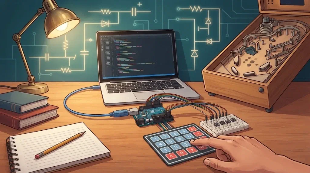
There will be 15 sensors on the playfield of our pinball machine: targets, lanes and the drain. On top of those there’s the Start button, so the main Arduino has to read 16 switches. An Arduino Uno has 18 pins that we can use freely, and the main Arduino also needs them for the tilt, for the link to the other Unos and for other jobs. If every switch had its own pin, there wouldn’t be enough pins.
That’s why we arrange the switches in a matrix: in rows and columns, like the cells of a table. Then 8 pins are enough for 16 switches. Today we’ll write a program that reads a matrix like this, meet its biggest trap, ghost keys, and fix it with diodes.
What does this mean for the pinball machine?
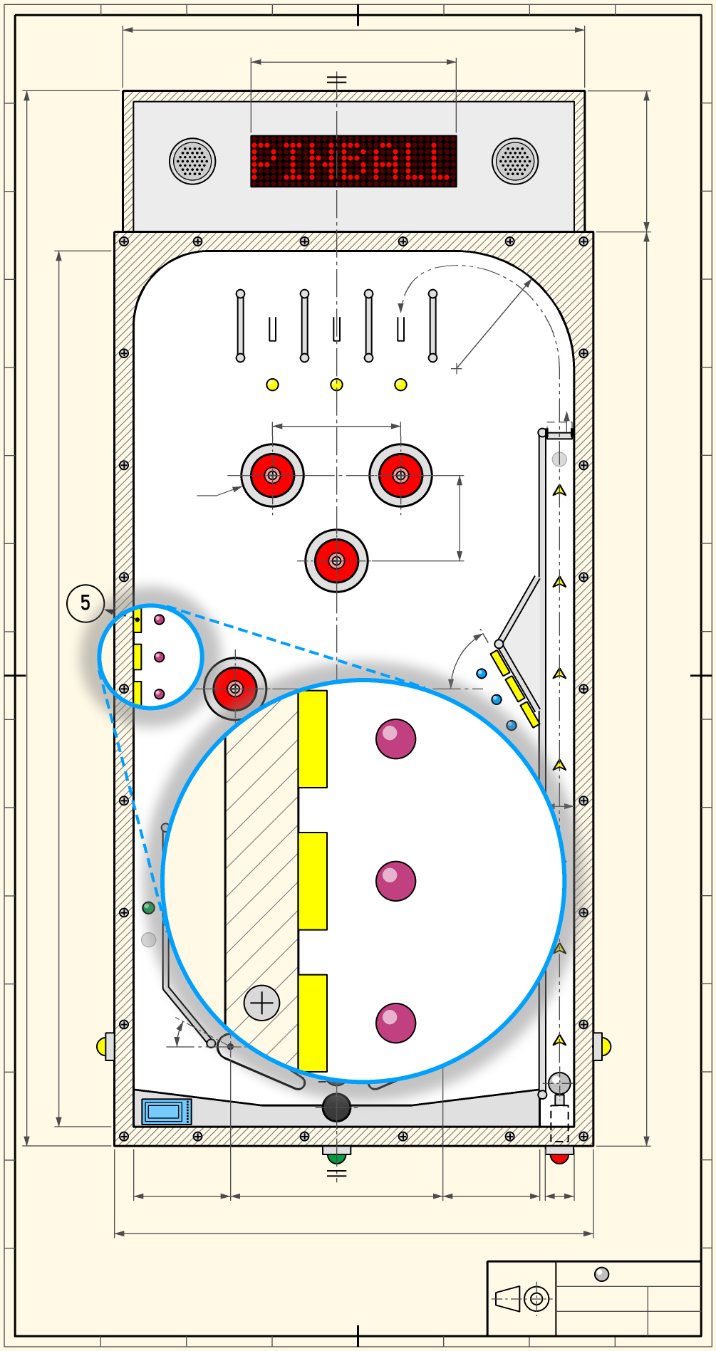
On the top view of our pinball machine, a blue circle marks the three targets on the left wall, and the large circle shows the same targets enlarged. Behind each target is a microswitch, and in front of it a lamp. The pinball page explains the other parts of the drawing.
- The pinball machine's main Arduino reads 15 sensors and the Start button through a 4 × 4 matrix, over 8 pins. A diode will be soldered next to every switch, as in Exercise 4, because the ball and the player can press several switches at the same time.
- The program scans the whole matrix in less than half a millisecond. The ball's hit on a microswitch lasts a few milliseconds, so the program is sure to see it. We'll measure it in the next lesson. That's why
loop()mustn't wait here either. - Every switch in the matrix has its own debouncing that reacts to the first contact, as today.
- We read the matrix with our own code from Exercise 1, not with the Keypad library from Exercise 3. The end of that exercise says why.
- The tilt and the flipper buttons aren't in the matrix. The tilt has its own pin, and the flipper buttons are connected to the Arduino that drives the flippers, because a flipper must move the moment the button is pressed.
How a matrix works
A 4 × 4 membrane keypad has 16 keys but only 8 legs. Inside there are four conductors in rows (R1 to R4) and four in columns (C1 to C4). Each key sits where one row crosses one column. When you press it, it connects that row with that column.
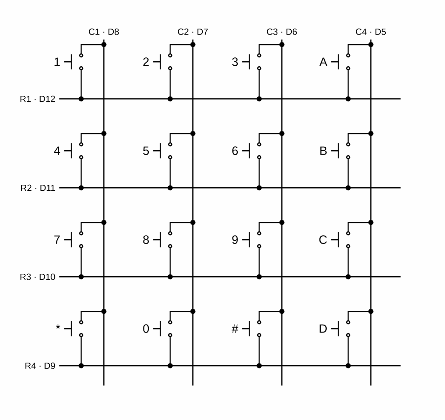
The Arduino reads the keypad row by row:
- It connects one row to GND: that row’s pin is an output and sends
LOW. The other rows are switched off. - It reads all four columns. The columns have a pull-up resistor, like a button, so they read
HIGH. A column that readsLOWis connected to the switched-on row through a pressed key. - It switches that row off and moves on to the next one.
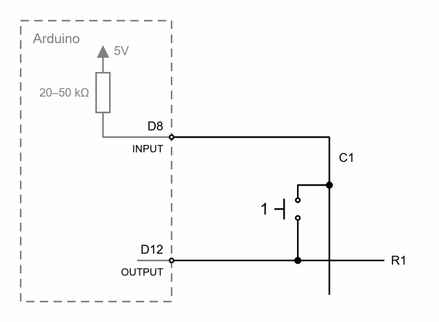
The picture shows one key close up. What’s inside the Arduino is drawn in grey (the dashed box): the built-in pull-up resistor of 20 to 50 kΩ connects the pin of column C1 to 5 V. While key 1 is released, no current flows through the resistor and the column reads HIGH. When you press it while row R1 is LOW, the key connects the column with the row, so the column reads LOW.
The row and the column together say which key is pressed: LOW on column C2 while row R1 is switched on means key 2. Reading the whole keypad like this is called scanning. The Arduino scans it in less than half a millisecond, so it repeats this thousands of times a second.
| Switches | Each on its own pin | In a matrix |
|---|---|---|
| 16 | 16 pins | 4 rows + 4 columns = 8 pins |
| 64 | 64 pins | 8 rows + 8 columns = 16 pins |
A row that is switched off isn't HIGH
The program doesn't set a row it isn't scanning to HIGH; it turns it into an input (INPUT). Then it isn't connected to anything, and no current can flow through it.
If a switched-off row were HIGH, two pressed keys in the same column would connect a row that sends HIGH with a row that sends LOW. That would be a short circuit between two pins, and it can damage the Arduino.
Materials
Each participant gets:
- an Arduino Uno and a USB cable
- a 4 × 4 membrane keypad and 8 jumper wires with pins on both ends
- a large breadboard, four small buttons, four diodes and jumper wires
For the demonstration in Exercise 1, the leader needs a two-channel oscilloscope with two probes, a small breadboard and a few jumper wires.
We don’t need the circuit from the last lesson any more: take it apart and put the parts back in the box.
Wiring rules
- While we wire, the Arduino is unplugged from the USB cable.
- Upload the program first, and only then connect the keypad. The Arduino may still have some old program on it in which the keypad’s pins are outputs, for example the traffic light program. If a program like that ran while you pressed keys, it could connect two outputs. So upload the program from Exercise 1 while nothing is connected to the Arduino yet.
- Before switching on, the leader checks the wiring.
Exercise 1: Scanning the keypad
The program
This program reads the keypad and prints the character of every key you press in the Serial Monitor. We’ll use the same program in Exercises 2 and 4 too.
// C++
const unsigned long DEBOUNCE_TIME = 50;   // after a change, we don't look at that key for 50 ms
const char NO_KEY = 0;                    // getKey() returns this when no key has just been pressed

const int rows[4] = {12, 11, 10, 9};      // legs 1 to 4 of the keypad: rows R1 to R4
const int columns[4] = {8, 7, 6, 5};      // legs 5 to 8 of the keypad: columns C1 to C4

// The character of each key: the first number is the row, the second the column.
const char keys[4][4] = {
  {'1', '2', '3', 'A'},
  {'4', '5', '6', 'B'},
  {'7', '8', '9', 'C'},
  {'*', '0', '#', 'D'}
};

bool wasPressed[4][4];                    // what each key was like last time (none at the start)
unsigned long lastChange[4][4];           // when each key last changed

// Scans the keypad and returns the character of the key just pressed, or NO_KEY.
char getKey() {
  for (int r = 0; r < 4; r++) {        // each row in turn
    pinMode(rows[r], OUTPUT);          // switch the row on: an output...
    digitalWrite(rows[r], LOW);        // ...connected to GND
    delayMicroseconds(10);             // wait for the voltage on the columns to settle

    for (int c = 0; c < 4; c++) {      // each column in turn
      bool pressed = digitalRead(columns[c]) == LOW;
      if (pressed != wasPressed[r][c] && millis() - lastChange[r][c] >= DEBOUNCE_TIME) {
        wasPressed[r][c] = pressed;
        lastChange[r][c] = millis();
        if (pressed) {                 // the key has just been pressed
          pinMode(rows[r], INPUT);     // switch the row off before returning
          return keys[r][c];           // return the character and leave the function
        }
      }
    }

    pinMode(rows[r], INPUT);           // switch the row off before the next one
  }
  return NO_KEY;                       // no key has just been pressed
}

void setup() {
  for (int r = 0; r < 4; r++) {
    pinMode(rows[r], INPUT);           // the row is switched off
  }
  for (int c = 0; c < 4; c++) {
    pinMode(columns[c], INPUT_PULLUP); // we read the column, like a button
  }
  Serial.begin(9600);
}

void loop() {
  char key = getKey();                 // the character of the key just pressed, or NO_KEY
  if (key != NO_KEY) {
    Serial.println(key);
  }
}
Upload the program while nothing is connected to the Arduino yet.
What’s new in the program?
const int rows[4] = {12, 11, 10, 9};– An array: one variable with several values, here four pin numbers. We get to each value by its position in square brackets, and we count from zero:rows[0]is 12, androws[3]is 9.const char keys[4][4]– A two-dimensional array: a table with four rows and four columns.keys[1][2]is the character in row 1 and column 2, so'6', because here too we count from zero. The typecharstores one character, written in single quotes:'6','#'.bool wasPressed[4][4];andunsigned long lastChange[4][4];– Each of the 16 keys remembers its own state and the time of its last change, like a single button in the lesson on buttons. Arrays written abovesetup()are full of zeros at the start, so no key is pressed.char getKey()– Our own function that returns a value, likereadStepCount()in lesson 2.1.charin front of the name says that the function returns one character. We’ve moved the whole scan into the function, soloop()is short. We named it getKey, because that’s also the name of the library’s function in Exercise 3. That’s whyloop()looks almost the same in both exercises.const char NO_KEY = 0;– A character that means no key.getKey()returns it when no key has just been pressed, and thenloop()prints nothing.for (int r = 0; r < 4; r++)and inside itfor (int c = 0; c < 4; c++)– A loop inside a loop. For each of the four rows, the inner loop goes through all four columns, so when the whole keypad is scanned, the body of the inner loop runs 16 times, once for each key.return keys[r][c];–returnreturns the character and leaves the function at once, even though both loops are still in the middle of their work. That’s why we switch the row off first. Otherwise it would stay switched on, and the program would see its keys while scanning other rows too.- If two new keys appear in the same scan,
getKey()returns the first one. The second one’s state hasn’t been remembered yet, so on the next pass throughloop()the function sees it as new again and returns it then. That way the program doesn’t miss any key. pinMode(rows[r], OUTPUT);…pinMode(rows[r], INPUT);– We change a row’s pin between output and input while the program runs, not only insetup(). As an output withLOW, the row is switched on, and as an input it is switched off.delayMicroseconds(10);– Waits 10 microseconds, a hundredth of a millisecond, for the voltage on the columns to settle after the row is switched on. It doesn’t make the program noticeably slower.- Each key’s debouncing is the same as in Exercise 3 of the lesson on buttons: the first change counts at once, and then we don’t look at that key for 50 ms.
Wiring
We look at the keypad’s legs from the front, with the keys facing us: legs 1 to 4 are the rows, and legs 5 to 8 the columns. Connect them in order to pins D12 to D5. Push one end of a jumper wire into the keypad’s connector and the other end straight into the Arduino’s pin. We don’t need the breadboard yet.
| Keypad leg | 1 | 2 | 3 | 4 | 5 | 6 | 7 | 8 |
|---|---|---|---|---|---|---|---|---|
| Conductor | R1 | R2 | R3 | R4 | C1 | C2 | C3 | C4 |
| Arduino pin | D12 | D11 | D10 | D9 | D8 | D7 | D6 | D5 |
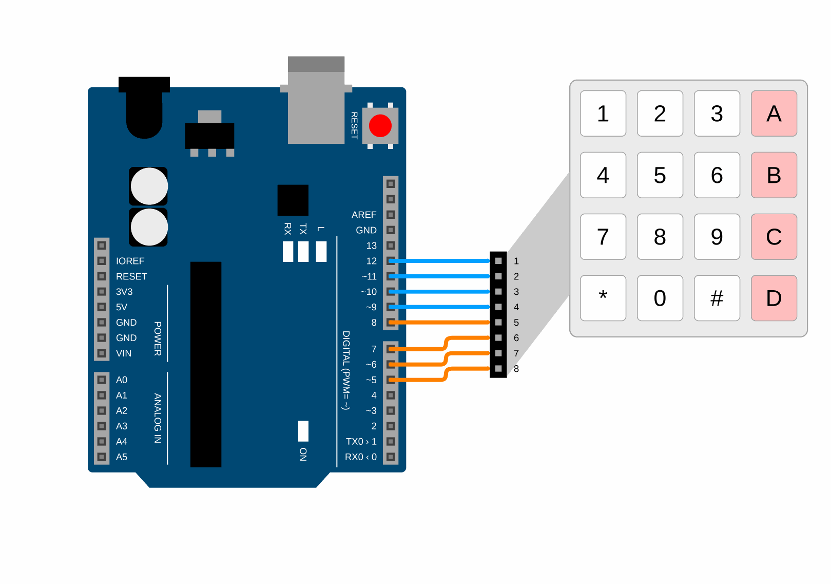
Most 4 × 4 membrane keypads have their legs in this order. If yours is different, the program will print the wrong characters. The section If something doesn’t work says how to fix that.
Plug in the USB cable, open the Serial Monitor (9600 baud) and press all the keys in turn. Does the program print the right character for every key?
Demonstration: an oscilloscope on the columns
The leader does this demonstration, and everyone watches. An oscilloscope draws how the voltage on a pin changes over time. Unlike a multimeter, it also sees changes that last only a few microseconds, so with it we can watch the scan as it happens. Our oscilloscope has two channels, CH1 and CH2, so it draws two pins at the same time: columns C1 and C2. The parts of our oscilloscope and the basic instructions are on the Oscilloscope page.
The ground clip goes only on GND
Each probe has a tip and a small crocodile clip for ground. Inside the oscilloscope, the grounds of both probes are connected to each other. If one clip were on GND and the other on some other pin, the oscilloscope would connect that pin to GND. That would be a short circuit. So both clips go on GND, and only the probe tips go on pins.
Getting ready:
- Unplug the USB cable. The leader doesn’t plug the wires of columns C1 and C2 straight into the Arduino, but through a breadboard: the wire from the keypad goes into its own row of the breadboard, and another wire goes from the same row to pin D8 (or D7). Into each of those two rows the leader pushes one more short wire, and hooks the probe tip onto its free end. One more wire connects the Arduino’s GND to a third row of the breadboard, for the grounds.
- Hook the tip of the CH1 probe onto column C1, and the tip of the CH2 probe onto column C2. Clip both ground clips onto the row with GND.
- The switch on the probe (1X or 10X) and the probe setting in the oscilloscope’s menu must be the same, for both channels. Usually it’s 10X.
- Set both channels to 2 V per division. Move CH1 to the top half of the screen and CH2 to the bottom half, so the traces don’t overlap.
- Set the time base to 50 µs per division.
- The trigger tells the oscilloscope when to start drawing. Set the source to CH1, the falling edge and the level to about 2.5 V: the oscilloscope draws from the moment the voltage on CH1 drops below 2.5 V. Use the MODE button to choose Auto mode, in which the oscilloscope draws even when there’s no trigger.
- Plug in the USB cable.
The demonstration:
- No key is pressed. Both traces are flat lines at 5 V.
- A participant holds key 1. The leader uses the MODE button to choose Normal mode: now the oscilloscope only draws when CH1 drops below 2.5 V, so the picture stands still. CH1 shows short drops to 0 V, one after another. The distance between two drops is one scan of the whole keypad. Is it shorter than half a millisecond, that is, than 10 divisions?
- A participant holds keys 1 and 2. The drops on CH1 and CH2 happen at the same time.
- A participant holds keys 1 and 5. The drop on CH2 starts about when the drop on CH1 ends.
- Catching a press. The participant lets go of all the keys, and the leader uses the MODE button to choose Single mode. The oscilloscope waits. When the participant presses key 1, the oscilloscope draws the moment of the press and stops. If the contacts bounce when the key is pressed, some of the first drops are missing or shorter than the rest.
The oscilloscope’s channel tells us the column, and the time of the drop tells us the row. That’s also how the program knows which key is pressed.
Which character is keys[2][1]?
'8'. We count from zero, so [2] is the third row ('7', '8', '9', 'C'), and [1] the second column in it.Why are both columns at 5 V on the oscilloscope while no key is pressed?
INPUT_PULLUP), and it holds them at 5 V. A switched-on row at LOW could pull a column down to 0 V only through a pressed key.You hold key 1 all the time. Why is column C1 at 0 V only in short drops?
LOW only while the program is scanning it. The rest of the time R1 is switched off (INPUT), so the pull-up holds C1 at 5 V. Each drop is a moment when the program switches row R1 on, once in every scan.Why do the drops of keys 1 and 2 happen at the same time, while the drop of key 5 comes right after the drop of key 1?
How can you read from the oscilloscope how long one scan of the keypad takes?
What would a multimeter show on column C1 while you hold key 1?
Exercise 2: Ghost keys
The program and the wiring stay the same. Press key 1 and hold it. Then press and hold key 2, and while you hold both, press key 4 as well. What does the program print?
Besides 1, 2 and 4, the program also prints 5, although nobody touched key 5. That’s a ghost key.
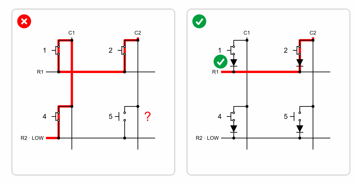
Look at the left side of the drawing. The program has switched on row R2 and is reading column C2. Key 5 isn’t pressed, but the current has found a way round (in red): from column C2 through key 2 into row R1, then through key 1 into column C1 and through key 4 into row R2. So column C2 reads LOW, and the program thinks key 5 is pressed.
The right side of the drawing shows how to fix this: next to each key there’s a diode, which lets current through in one direction only, from the column to the row. Current from column C2 still gets through key 2 into row R1, but the way round would have to go through key 1 backwards, from row R1 to column C1. Key 1’s diode doesn’t allow that (green tick), so column C2 stays at 5 V and there is no ghost key. We’ll add the diodes in Exercise 4.
A ghost key appears when three keys are pressed in three corners of a rectangle in the matrix. The fourth corner is then a ghost key.
You hold keys 5, 6 and 8. Which ghost key will appear?
Ghost keys on a computer
A computer keyboard is a matrix too. Cheap keyboards have no diodes, so some combinations of three or more keys don't work properly: the computer either sees a key you didn't press or doesn't see one you did. That's why gaming keyboards often have a diode next to every key, so the computer correctly sees any combination of keys.
Exercise 3: The keypad with the Keypad library (optional)
Do this exercise if you have time left. Keypads are so common that there’s a ready-made library for them, like Bounce2 for the button in the lesson on buttons. It’s called Keypad. We’ll write a program that does the same as the program from Exercise 1, but we’ll leave the scanning and the debouncing to the library. Then we’ll see what the library does with ghost keys.
The wiring stays the same, so you don’t need to disconnect the keypad. The library, too, has only one pin as an output at any moment, so it can’t connect two outputs.
Installing the library
- In the Arduino IDE, open the Library Manager: the icon with books on the left, or the menu Sketch ⇒ Include Library ⇒ Manage Libraries…
- Type Keypad in the search box.
- Install the library called just Keypad, by Mark Stanley and Alexander Brevig. The search also shows many other libraries with the word Keypad in their name, but we don’t need them.
Installing needs the internet. If the workshop has none, the leader installs the library on every computer beforehand.
The second part of the plan is the same as in Exercise 1; we only ask the library instead of our function. The first part of the plan, the function getKey, is now in the library.
The program with the library
// C++
#include <Keypad.h>                    // the library for keypads

byte rows[4] = {12, 11, 10, 9};        // the same pins as in Exercise 1
byte columns[4] = {8, 7, 6, 5};

char keys[4][4] = {
  {'1', '2', '3', 'A'},
  {'4', '5', '6', 'B'},
  {'7', '8', '9', 'C'},
  {'*', '0', '#', 'D'}
};

Keypad keypad(makeKeymap(keys), rows, columns, 4, 4);

void setup() {
  Serial.begin(9600);
}

void loop() {
  char key = keypad.getKey();          // the character of the key just pressed, or NO_KEY
  if (key != NO_KEY) {
    Serial.println(key);
  }
}
Upload the program, open the Serial Monitor and press all the keys in turn. The program must print the same characters as the program from Exercise 1.
What’s new in the program?
#include <Keypad.h>– Includes the library in the program. If the library isn’t installed, compiling gives the errorKeypad.h: No such file or directory.byte rows[4] = {12, 11, 10, 9};– The typebytestores a whole number from 0 to 255, which is enough for a pin number. The library wants the pins in an array of typebyte, and withoutconst, so here we can’t writeconst intas in Exercise 1.Keypad keypad(makeKeymap(keys), rows, columns, 4, 4);–keypadis an object, likestartin the lesson on buttons. We tell the library the characters of the keys, the row pins, the column pins, and how many rows and columns there are.makeKeymap()turns our table of characters into the form the library wants.setup()has onlySerial.begin(9600);– The library sets up the pins, so we don’t writepinMode().char key = keypad.getKey();– The library’sgetKey()function does the same as ours from Exercise 1: it scans the keypad and returns the character of the key that has just been pressed, and if there’s no such key, it returnsNO_KEY. We writekeypad.in front of it, because it’s a function of the object. Apart from that,loop()is the same as in Exercise 1.- There’s no
getKey()function of our own, noNO_KEYconstant, and nowasPressedandlastChangearrays. The library has all of that.
Advantages of the library:
- The program is much shorter and easier to read. All that’s left from Exercise 1 is the pins, the table of characters and
loop(). - Debouncing is already built in, so we don’t have to write it.
- The library knows more than presses: for every key it knows whether it has just been pressed, whether someone has been holding it for longer than half a second, or whether it has just been released. That comes in handy for a combination lock or a menu.
- A keypad of another size, for example a 4 × 3 phone keypad, only needs other numbers and another table of characters.
- Many people use the library, so most of its bugs have already been found and fixed. The menu File ⇒ Examples ⇒ Keypad has ready-made examples.
The disadvantages are the same as with the Bounce2 library: it has to be installed on every computer, we can’t see how it works, and it takes up more memory. This program is about 830 bytes bigger than the program from Exercise 1.
Ghost keys with the library
Repeat the experiment from Exercise 2: press and hold key 1, then key 2, and while you hold both, press key 4 as well. What does the program print now?
The program prints only 1. There’s no ghost key 5, but there are no keys 2 and 4 either, although you really pressed them.
The library doesn’t remove ghost keys. It also scans a keypad without diodes, so it too reads LOW for key 5, like our program in Exercise 2. From the voltages on the pins, there’s no way to tell whether key 5 is really pressed or the current has found a way round. No program can do that.
We don’t see the ghost key because of the way the library’s getKey() works. The library keeps the pressed keys in a list, and getKey() only reports a new key in the first place on the list. While you hold key 1, it’s the first, so getKey() reports neither 2, nor 4, nor the ghost 5. The function getKeys() from the same library reports all the pressed keys, so besides 1, 2 and 4 it would also report the ghost key 5.
At most, a program could notice that three keys in the corners of a rectangle are pressed and not trust the fourth, like some cheap computer keyboards, which then prefer not to see one key. The Keypad library doesn’t even do that. Only diodes really remove ghost keys, and we’ll add them in Exercise 4.
Did the Keypad library remove the ghost key?
LOW for key 5. It doesn’t print the ghost key only because, while you hold key 1, getKey() doesn’t report any other key, so it doesn’t report the real keys 2 and 4 either. With the function getKeys(), the ghost key 5 would appear.Why we don’t use it in the pinball machine
For a keypad that a person presses, the Keypad library is a good choice. Still, the pinball machine’s main Arduino will read the matrix with our code from Exercise 1, because the library does three things that get in the pinball machine’s way:
- It scans the keypad at most once every 10 ms. If 10 ms haven’t passed since the last scan,
getKey()returnsNO_KEYstraight away, without even looking at the keypad. That’s how the library debounces the keys. A finger holds a key much longer, so that doesn’t matter. The ball’s hit on a microswitch lasts only a few milliseconds and can pass completely between two scans. Then the program doesn’t see it at all. Our program scans the whole matrix on every pass throughloop(). - The library’s
getKey()reports only one key. While you hold key 1, the library’sgetKey()doesn’t report other keys, as you saw in the experiment with ghost keys. OurgetKey()from Exercise 1 does. In the pinball machine, the ball and the player often press several switches at the same time. The library also has a functiongetKeys()for several keys, but with it the program isn’t short any more. - It scans in the opposite direction. Our program switches on the rows and reads the columns, so current flows through a pressed key from the column to the row. The library switches on the columns (
LOW) and reads the rows (pull-up), so current flows from the row to the column. In Exercise 4 we’ll add diodes that only let current through from the column to the row. With them, the library wouldn’t see any key until we swapped the rows and columns in the program.
Why can the Keypad library miss the ball's hit in the pinball machine?
Exercise 4: Diodes against ghost keys
A diode is a one-way valve for current: it lets it through in one direction only, from the anode to the cathode. You already know one diode well: an LED is a diode that lights up as it does this. On an ordinary diode, the cathode is marked with a stripe.
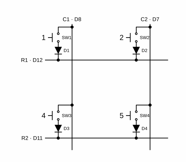
In our matrix, current flows through a pressed key from the column, which the pull-up resistor holds at 5 V, to the switched-on row at LOW. So we put a diode next to each key: the anode towards the key, and the cathode towards the row. Current then flows through a pressed key just as before. But the way round has to go through key 1 backwards, from the row to the column, and the diode doesn’t allow that. Look at the right side of the drawing from Exercise 2, repeated here:
We can’t add diodes to the keypad, so we’ll build a small 2 × 2 matrix on the breadboard, with four buttons and four diodes.
Wiring
The program is the one from Exercise 1. If you did Exercise 3, first upload the program from Exercise 1 again, because the library scans in the opposite direction and wouldn’t see any key with these diodes. Then unplug the USB cable and pull the wires out of the keypad. Our small matrix is connected to the first two rows and the first two columns, so to the program its buttons are keys 1, 2, 4 and 5. The other pins stay unconnected, and the program doesn’t see any key on them.
| Part | Arduino pin | On the breadboard |
|---|---|---|
| Button 1 | – | across the centre gap, in e3, e5, f3, f5 |
| Button 2 | – | across the centre gap, in e9, e11, f9, f11 |
| Button 4 | – | across the centre gap, in e15, e17, f15, f17 |
| Button 5 | – | across the centre gap, in e21, e23, f21, f23 |
| Diodes | – | h5–h8, h11–h14, h17–h20 and h23–h26; stripe (cathode) at the bottom, in rows 8, 14, 20 and 26 |
| Column C1 | D8 | wire from D8 to a3, wire from b3 to b15 |
| Column C2 | D7 | wire from D7 to a9, wire from c9 to c21 |
| Row R1 | D12 | wire from D12 to f8, wire from i8 to i14 |
| Row R2 | D11 | wire from D11 to f20, wire from i20 to i26 |
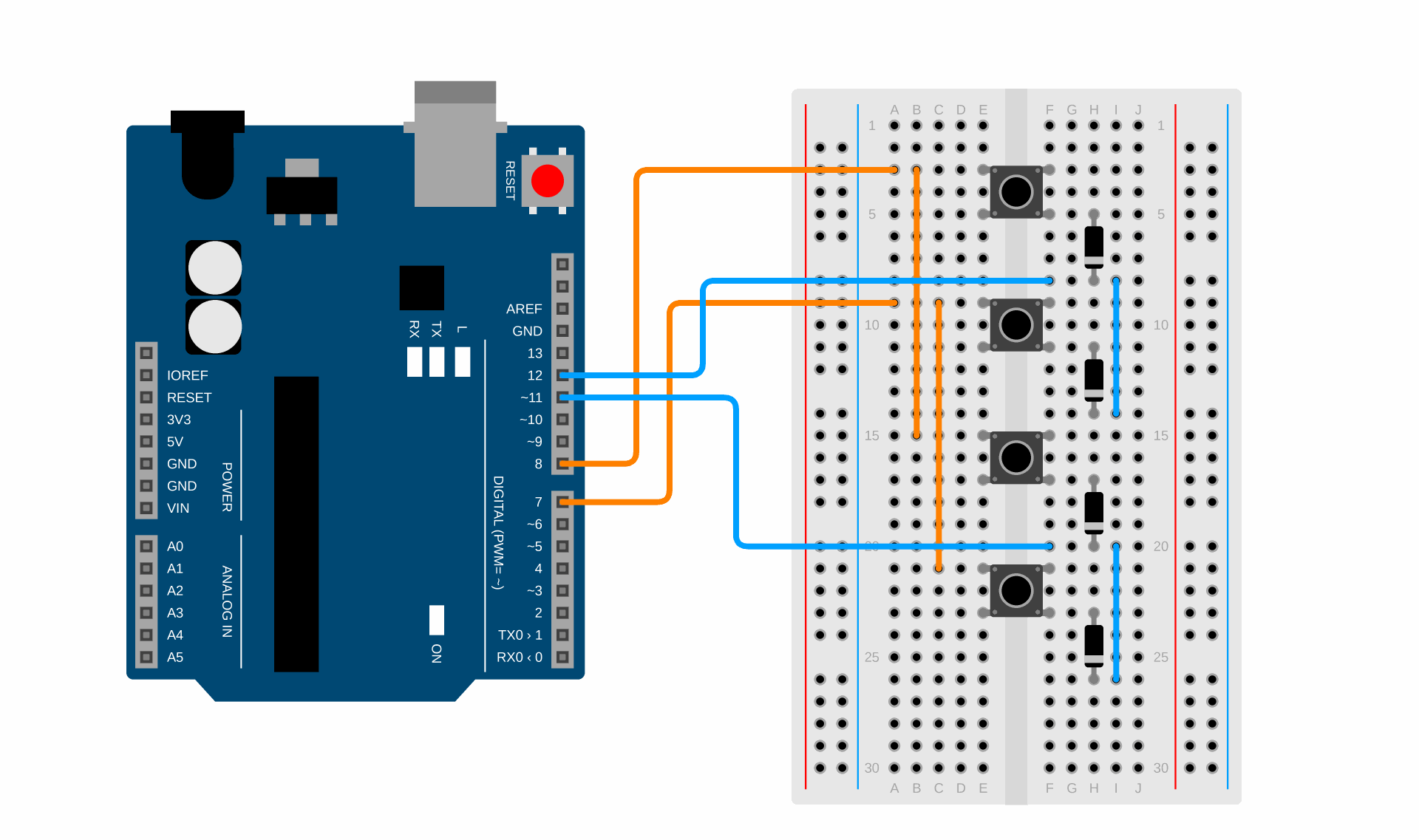
- Each button connects its two rows of the breadboard, for example button 1 rows 3 and 5. Row 3 leads to the column, and row 5 through the diode to the row of the matrix.
- The matrix doesn’t need GND on the breadboard. The switched-on row of the matrix, a pin with
LOW, is the same as GND for the keys. - A diode keeps about half a volt across itself, so the column of a pressed key doesn’t drop all the way to 0 V. That’s still well below 1.5 V, so the Arduino is sure to read
LOW.
Plug in the USB cable and open the Serial Monitor. Press each button: does the program print 1, 2, 4 and 5? Then press and hold buttons 1, 2 and 4. Does the program also print 5?
Experiments
1. The diode is the protection. Unplug the USB cable, take out button 1’s diode and put a wire from h5 to h8 in its place. Plug in the USB cable and hold buttons 1, 2 and 4 again. What happens? Put the diode back.
2. A diode the wrong way round. Turn button 2’s diode round, so that the stripe is at the top, in h11. Does button 2 work? Turn it back.
Why is it button 1's diode that matters in experiment 1?
Why doesn't button 2 work with its diode the wrong way round?
HIGH, and the program doesn’t see the key.If something doesn’t work
- The program prints nothing ⇒ Choose 9600 baud. Are all the wires in the keypad’s connector? Do they go in order from legs 1 to 8 to D12 to D5?
- The program prints the wrong characters, for example 4 when you press 2 ⇒ On your keypad, the rows and columns are swapped. In the program, swap the numbers in the arrays: make
rows{8, 7, 6, 5}andcolumns{12, 11, 10, 9}. - The program prints the characters in reverse order, for example D when you press 1 ⇒ The wires are the wrong way round in the connector. Connect leg 1 to D12 and leg 8 to D5.
- A whole row or a whole column of keys doesn’t work ⇒ One wire isn’t pushed in properly. Find out from the table which one, and check it.
- In Exercise 4 one button doesn’t work ⇒ Is its diode the wrong way round? The stripe must be at the bottom, in row 8, 14, 20 or 26. Is the button across the centre gap?
- In Exercise 4 a ghost key still appears ⇒ A diode is missing or bridged by a wire. Check that all four diodes are in place.
- The program won’t upload ⇒ Check that the board Arduino Uno and the right port are selected in the Arduino IDE.
Extra challenges
- A combination lock. Let the program remember the last four keys pressed. When you press #, let it print Open if they were 1, 9, 7 and 0, and Wrong otherwise. Tip: store the four characters in an array
char code[4];. - How many keys at once? Every half a second, let the program print how many keys are pressed right now. On the keypad without diodes, try to find four keys that you can press at once without a ghost key appearing.
- How long does a scan take?
micros()works likemillis(), but returns microseconds. Use it to measure how long one scan of the whole keypad takes. Is it shorter than the ball’s hit, which lasts a few milliseconds?
 What did we learn?
- In a matrix, the switches are in rows and columns. 16 switches in a 4 × 4 matrix need only 8 pins.
- The Arduino scans the matrix: it switches one row on (
LOW), reads all the columns (INPUT_PULLUP), switches the row off and moves on to the next one. - On the oscilloscope, the column of a pressed key drops to 0 V briefly once in every scan, while that key’s row is switched on.
- A row that is switched off is an input (
INPUT), notHIGH. Otherwise two keys in the same column would connect two outputs. - An array is a variable with several values. We get to a value by its position, and we count from zero:
rows[0]. - A two-dimensional array is a table:
keys[row][column]. The typecharstores one character. - A loop inside a loop goes through all the rows, and in each of them through all the columns.
- Three pressed keys in three corners of a rectangle give a ghost key in the fourth corner, because the current finds a way round.
- The Keypad library scans the keypad for us, so the program is much shorter, but it doesn’t remove ghost keys. We don’t use it in the pinball machine, because it scans at most once every 10 ms and can miss a short hit of the ball.
- A diode lets current through only from the anode to the cathode. The stripe on a diode is the cathode.
- A diode next to each key stops the way round, so there are no ghost keys.
Quick quiz
1. How many pins does a matrix with 8 rows and 8 columns need, and how many switches can it have?
2. How does the program know which key is pressed?
LOW while a row is switched on, the key where that row crosses that column is pressed.3. Why is a switched-off row INPUT and not HIGH?
HIGH with a row at LOW. That’s a short circuit between two pins. An input isn’t connected to anything, so no current flows through it.4. Why do we upload the program first and only then connect the keypad?
HIGH with an output at LOW. Our program keeps the rows as inputs until it scans them, so it’s safe.5. What is rows[0] in the program from Exercise 1?
- We count from zero, so
rows[0]is the first value in the array{12, 11, 10, 9}: the pin of row R1.
6. How many times does the body of the inner loop run when getKey() scans the whole keypad?
7. When does a ghost key appear?
LOW, as if the fourth key were pressed too.