
LED matrix and MAX7219
An 8 × 8 LED matrix with the MAX7219 chip on the Arduino: multiplexing, our own send function with shiftOut(), a picture, an animation and scrolling text
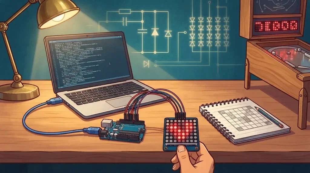
On the backbox above the playfield of our pinball machine there will be a display made of four LED matrices. On it the player will see the score, messages and small animations. Today we meet one matrix: 64 LEDs arranged in 8 rows and 8 columns.
If every LED had its own pin, the Arduino would need 64 pins, and only 18 are free. That’s why the LEDs are wired as a matrix, like the switches in the last chapter, and the matrix is driven by a chip called the MAX7219. The Arduino talks to it over just three wires. We’ll write our own function that sends data to the chip, draw a picture in the character generator, bring it to life with an animation, and finally scroll text across the matrix.
What does this mean for the pinball machine?
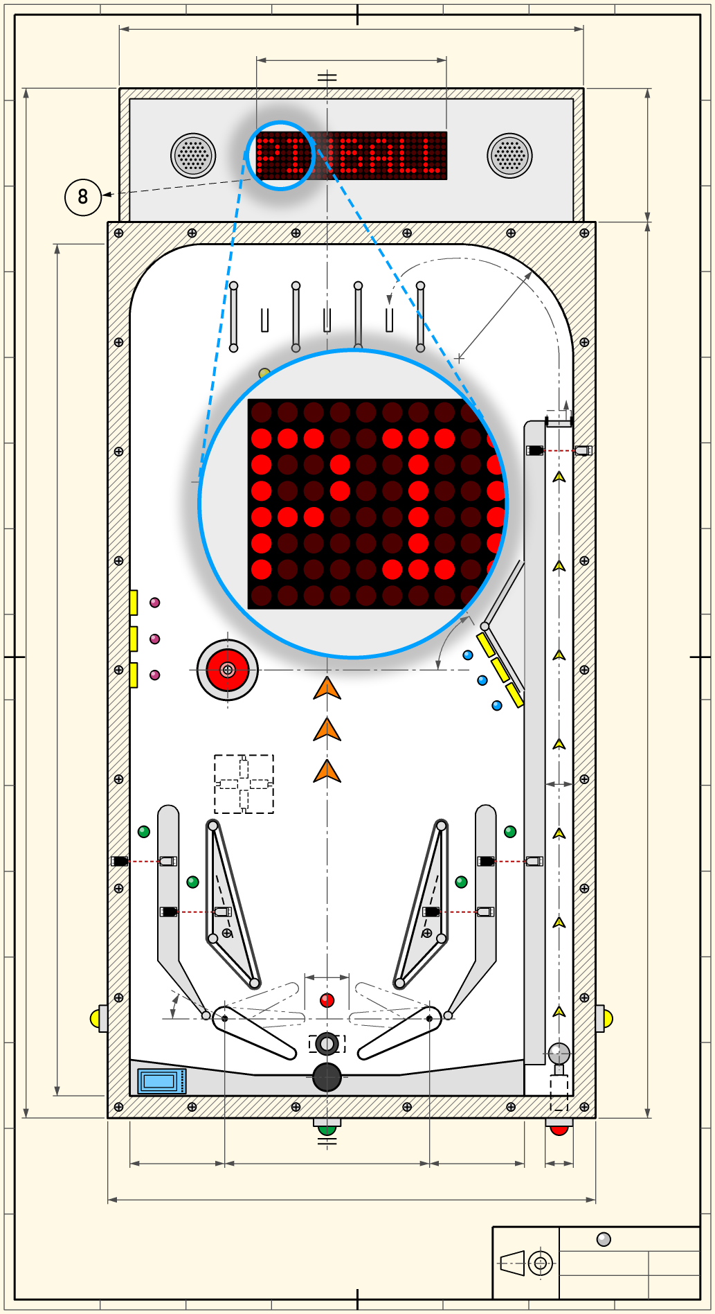
On the top view of our pinball machine, a blue circle marks the first of the four LED matrices on the backbox above the playfield, and the large circle shows the same matrix enlarged. The pinball page explains the other parts of the drawing.
- The pinball machine's display is four matrices like this one, joined in a chain. We'll learn how to chain matrices in the next lesson.
- The display is driven by the show Uno. For the whole display it needs only three pins, just like one matrix today.
- The same Uno also drives the servos and the sound, so an animation on the display mustn't wait with
delay(). We'll change the pictures withmillis(), as in Exercise 3. - The score and messages will scroll across the display like the text in Exercise 4, only over four matrices instead of one.
- One matrix with every LED lit at full brightness uses about 0.3 A. That's why the display in the pinball machine isn't powered by an Arduino but by a 5 V power supply.
How an LED matrix works
The matrix has 64 LEDs in 8 rows (R1 to R8) and 8 columns (C1 to C8). All the LEDs in one column share their anode, and all the LEDs in one row share their cathode. So the matrix has only 16 pins: 8 for the rows and 8 for the columns.
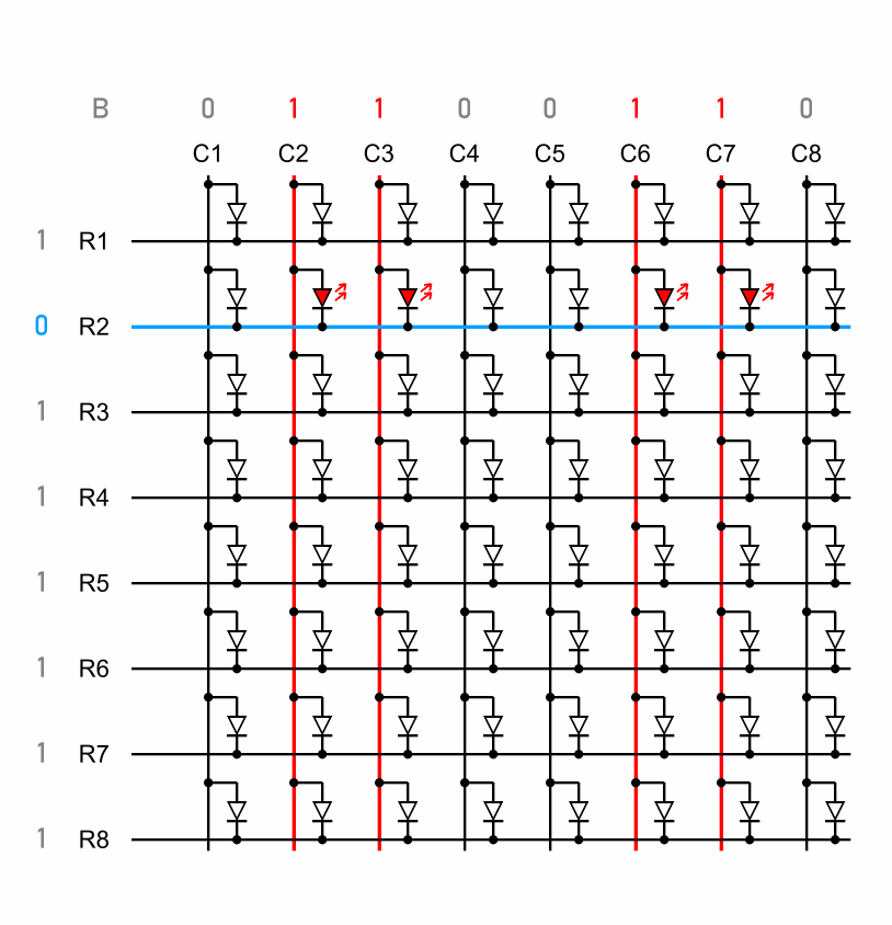
An LED lights when its column is switched on and its row is connected to GND. In the drawing, row R2 is switched on (blue) and so are columns C2, C3, C6 and C7 (red), so four LEDs light in row R2. The other rows aren’t switched on, so nothing lights in them.
Which columns are switched on is written above them: 1 means on and 0 means off. In the same way, the numbers left of the rows give each row’s voltage: 1 is 5 V and 0 is GND. Only R2 is switched on, so only it has a 0. The other rows are at 1, so no current flows through their LEDs. These are eight bits, so one byte: B01100110. Each row of the matrix is described by one byte, so a whole picture is described by eight bytes.
One row at a time
What if we switch on two rows at once, say R2 and R5? The columns are shared, so both rows would show the same pattern. We can’t show two different rows at the same time.
That’s why the rows are lit one at a time: first R1 with its pattern, then R2 with its own, and so on to R8, and then from the start again. This is called multiplexing. We did the same with the keypad in the lesson on the switch matrix, where we scanned it row by row.
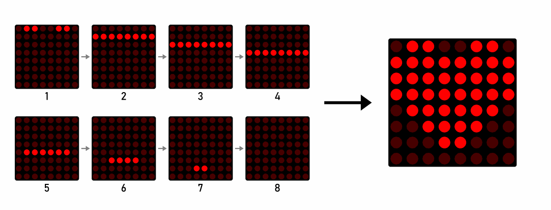
Each row lights only an eighth of the time, but the chip goes through all 8 rows about 800 times a second. That’s too fast for the eye, so it sees the whole picture, not rows taking turns. Many big LED screens in the street work the same way.
How many pins does an 8 × 8 LED matrix need, and how many would it need if every LED had its own two pins?
The MAX7219 chip
The Arduino could multiplex the matrix itself, but it would need 16 pins for it and would have to light row after row all the time. The instructor can show what that looks like in the optional demonstration at the end of the lesson. The MAX7219 chip does that job for it. It sits together with the matrix on a small module:
- It multiplexes the matrix by itself, about 800 times a second.
- It remembers the picture. It has eight registers, one for each row, and each holds one byte. The Arduino sends a picture once, and the chip shows it until it gets a new one.
- It limits the current of all the LEDs with one resistor, R1 in the schematic, so the LEDs don’t need resistors of their own.
- It changes the brightness in 16 steps.
On our module the chip and the matrix aren’t soldered, but plugged into sockets. So a broken chip or matrix can be taken out and replaced with a new one.
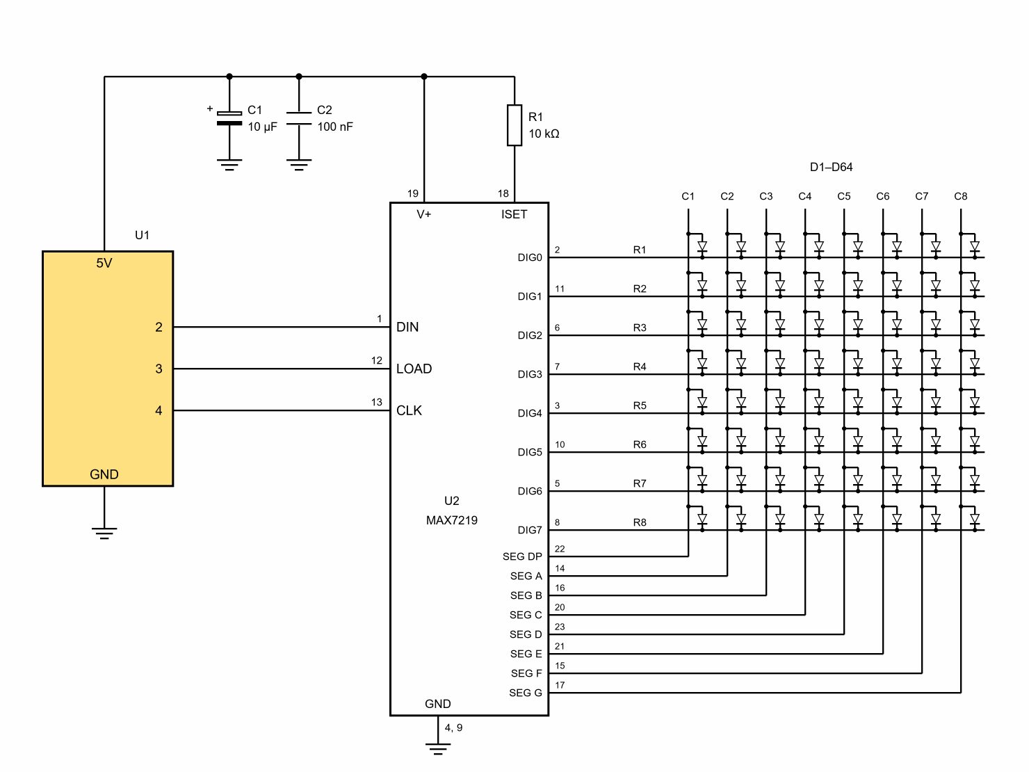
The MAX7219 was made for displays with seven-segment digits, like the ones on alarm clocks. That’s why its pins for the rows are called DIG0 to DIG7 (for digit) and its pins for the columns SEG A to SEG G and SEG DP (for segment). In the schematic the DIG pins go straight across into the rows of the matrix, and the SEG pins under the matrix and up into the columns. In the drawing of the chip the pins aren’t in the same order as on the chip itself, but arranged so that no lines cross. The real pin number is next to each line.
Resistor R1 sets how much current flows through the LEDs. Capacitors C1 and C2 next to the chip smooth the supply voltage: when a whole row of LEDs lights up, the current rises suddenly, and the capacitors supply part of it until the power supply catches up.
How the Arduino sends data
The Arduino is connected to the chip with three wires:
- DIN (data in): the data, bit by bit.
- CLK (clock): tells the chip when to read the next bit.
- CS (chip select): the frame around a message. On the chip this pin is called LOAD, and on the module CS.
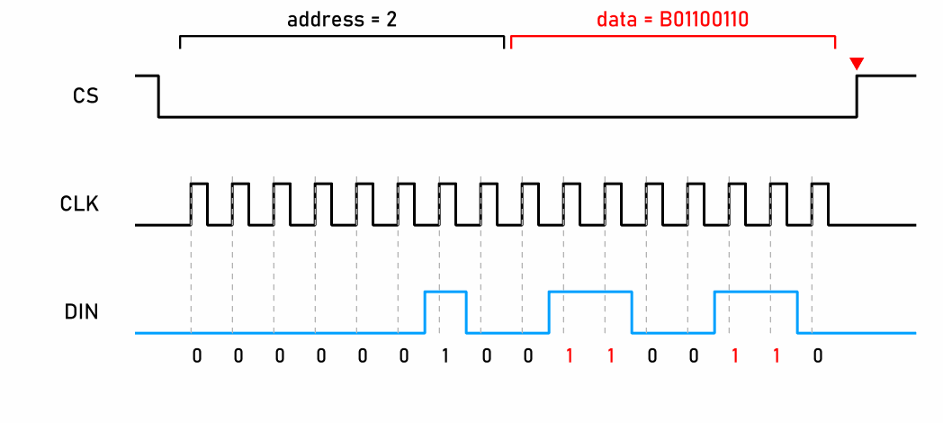
A message has 16 bits. First the Arduino sets CS to LOW. Then for each bit it sets DIN to 0 or 1 and sends one pulse on CLK. On each pulse the chip reads the bit from DIN and pushes the earlier bits one place along, like people in a queue at a checkout. A store of bits like this is called a shift register. When all 16 bits have been sent, the Arduino sets CS back to HIGH, and the chip then looks at what has arrived:
- The first 8 bits are the address: which register the chip writes the data into.
- The second 8 bits are the data: what it writes.
In the diagram the Arduino sends the address 2 and the data B01100110: in the second row, light the LEDs in columns C2, C3, C6 and C7. That’s the picture from the start of the lesson.
This way of sending is similar to the SPI connection, which many chips and modules use.
The chip also has registers that aren’t rows. We use these six:
| Address | Register | What we write |
|---|---|---|
| 1 to 8 | rows R1 to R8 | which LEDs in the row light, one byte |
| 9 | decoding | 0: each bit is one LED |
| 10 | brightness | 0 (dimmest) to 15 (brightest) |
| 11 | number of rows | 7: all eight rows, 0 to 7 |
| 12 | on | 1: the chip works, 0: the matrix is off |
| 15 | test | 1: every LED lights at full brightness, 0: normal operation |
When it gets power, the chip is switched off, and the row registers can hold anything. That’s why the program always sets it up first: it writes all the registers from the table, clears all the rows and only then switches it on.
What are the first eight bits of the message that sets the brightness?
00001010. The chip gets those eight bits first, and then the eight bits of the brightness.Materials
Each participant gets:
- an Arduino Uno and a USB cable
- a module with an 8 × 8 LED matrix and a MAX7219 chip
- five jumper wires with a socket on one end and a pin on the other (female–male)
For the demonstration in Exercise 1, the instructor needs an oscilloscope with two channels and two probes, a small breadboard and five male–male jumper wires.
For the optional demonstration at the end of the lesson, the instructor also needs another Arduino Uno with a USB cable, an 8 × 8 LED matrix without a module (for example a 1588BS), eight 1 kΩ resistors, a 10 kΩ potentiometer and jumper wires, and for the measurement the oscilloscope with its probes from Exercise 1.
We don’t need the circuit from the last lesson any more: take it apart and put the parts back in the box.
Wiring rules
- While we wire, the Arduino is unplugged from the USB cable.
- VCC goes to 5V and GND to GND. If you swap them, the chip can be damaged. Before it’s switched on, the instructor checks the wiring.
- The wires go on the module’s input header, the one marked DIN. The output header is marked DOUT. The next matrix in a chain connects to it. If you connect the Arduino to the output header, the matrix won’t work.
- Leave the brightness at 1, as it is in the program. The matrix then uses little current and doesn’t dazzle you.
Wiring
Push the socket end of each wire onto a pin of the module, and the pin end into the Arduino. We don’t need a breadboard.
| Module pin | VCC | GND | DIN | CS | CLK |
|---|---|---|---|---|---|
| Arduino pin | 5V | GND | D2 | D3 | D4 |
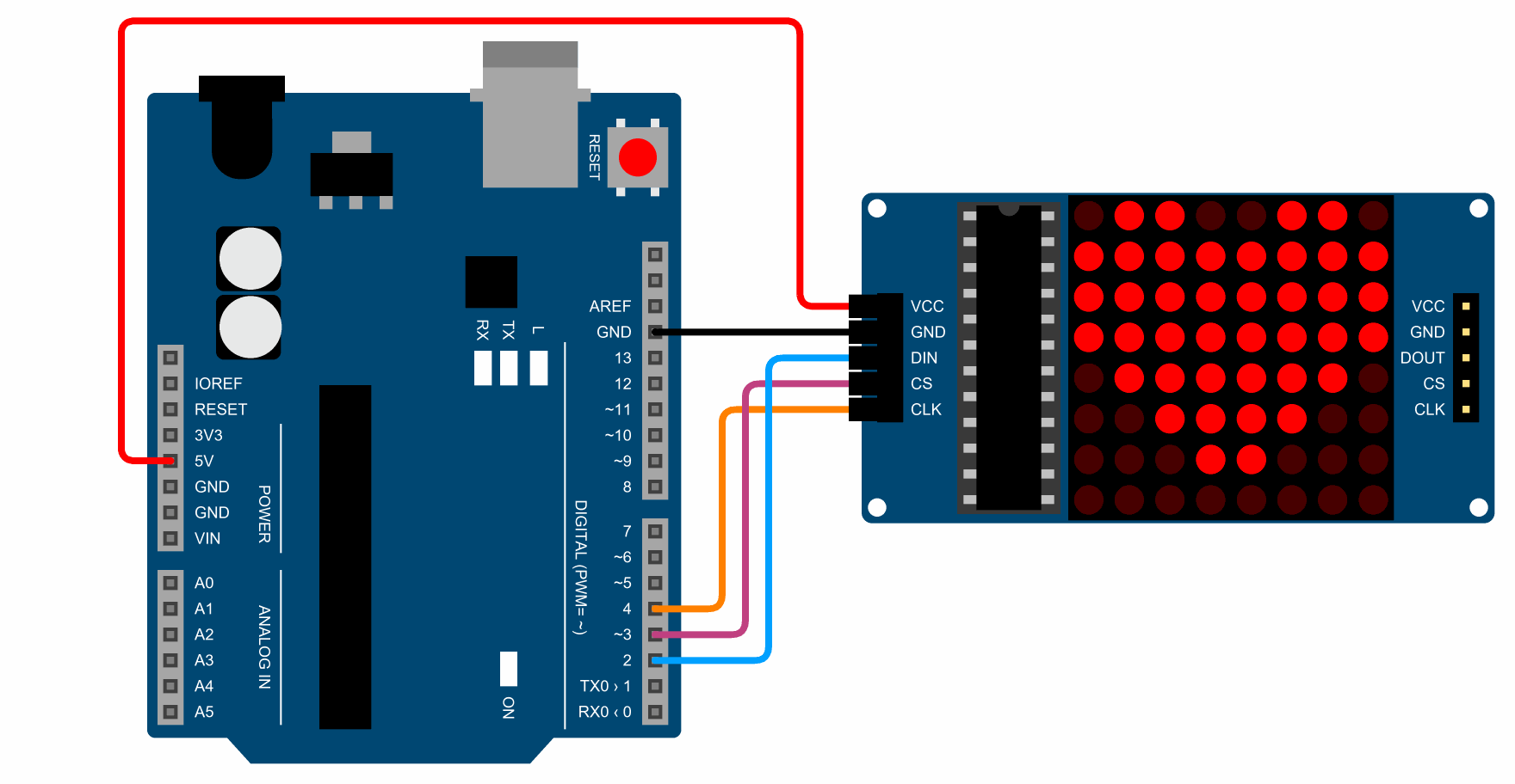
The input header is the one next to the chip, labelled DIN. Turn the module so that this header is on the left, as in the picture. Then the picture is upright, and in the next lesson a second matrix goes to its right. The chip doesn’t know which way the module is turned: its row R1 is always along the same edge of the matrix. If you turn the module another way, the picture turns too, and when the header is at the bottom, the rows become columns.
Exercise 1: The first LED
The program
The program sets up the chip and lights one LED, the top left one. All the talking to the chip is in our own function send(), which sends one message: an address and the data.
// C++
const int DIN = 2;              // data
const int CS = 3;               // frame of a message (LOAD on the chip)
const int CLK = 4;              // clock

// Addresses of the MAX7219's registers. Addresses 1 to 8 are the rows of the matrix.
const byte DECODE = 9;          // 0: each bit is one LED
const byte BRIGHTNESS = 10;     // 0 to 15
const byte ROW_COUNT = 11;      // 7: all eight rows
const byte POWER = 12;          // 1: on, 0: off
const byte TEST = 15;           // 1: every LED lights, 0: normal operation

// Sends the chip one message: writes the data into the register at the address.
void send(byte address, byte data) {
  digitalWrite(CS, LOW);                    // the message starts
  shiftOut(DIN, CLK, MSBFIRST, address);    // first 8 bits: the address
  shiftOut(DIN, CLK, MSBFIRST, data);       // second 8 bits: the data
  digitalWrite(CS, HIGH);                   // end of the message: the chip writes the data
}

void setup() {
  pinMode(DIN, OUTPUT);
  pinMode(CS, OUTPUT);
  pinMode(CLK, OUTPUT);
  digitalWrite(CS, HIGH);                   // between messages CS is HIGH

  send(TEST, 0);                            // normal operation
  send(DECODE, 0);                          // each bit is one LED
  send(ROW_COUNT, 7);                       // all eight rows
  send(BRIGHTNESS, 1);                      // dim light
  for (byte row = 1; row <= 8; row++) {
    send(row, 0);                           // clear the row
  }
  send(POWER, 1);                           // switch the matrix on

  send(1, B10000000);                       // row 1: the first LED from the left
}

void loop() {
}
When the module is wired up, plug in the USB cable and upload the program. Does the top left LED light?
What’s new in the program?
const byte DECODE = 9;– Thebytetype stores a whole number from 0 to 255, so exactly eight bits. The chip’s addresses and data are bytes, so we store them in this type. The registers have names, so in the program we writesend(BRIGHTNESS, 1)instead of a puzzlingsend(10, 1).void send(byte address, byte data)– Our own function with two parameters. Like the functions in the traffic light lesson, but when we call it, we give it two numbers in the brackets:send(1, B10000000). Inside the function the first number is calledaddressand the seconddata.shiftOut(DIN, CLK, MSBFIRST, address);– A built-in Arduino function that sends one byte, bit by bit: for each bit it sets theDINpin and sends one pulse on theCLKpin. That’s exactly what the chip expects.MSBFIRST(most significant bit first) means that it sends the highest bit, the one on the far left, first.B10000000– A binary number in the program: the letterBand eight bits. The bit on the far left is column C1, and the bit on the far right column C8. We could have written128instead, but in binary we can see straight away which LEDs light. There’s more about binary numbers on the Binary, octal and hexadecimal numbers page.for (byte row = 1; row <= 8; row++)– The loop writes 0 into all eight row registers, addresses 1 to 8. We count from 1, because these are register addresses.loop()is empty. We sent the picture once, and the chip shows it by itself.
Try it:
- Light the bottom right LED:
send(8, B00000001); - Light the whole fourth row:
send(4, B11111111); - Light the two middle LEDs in row 5.
- Set the brightness to 0, then to 15. Can you see the difference? Then set it back to 1.
Add the calls from these tasks at the end of setup(), below the first LED.
If the picture isn’t the right way round, see If something doesn’t work.
Which call lights the two middle LEDs in row 5?
send(5, B00011000);. The middle LEDs are in columns C4 and C5, which are the fourth and fifth bits from the left.Demonstration: a message on the oscilloscope
The instructor does this demonstration and everyone watches. With the oscilloscope we’ll catch the first message the program sends to the chip and read it bit by bit. The parts of our oscilloscope and the basic instructions are on the Oscilloscope page.
The ground clip goes only on GND
The grounds of both probes are connected together inside the oscilloscope. If one clip were on GND and the other on some other pin, the oscilloscope would connect that pin to GND. That would be a short circuit. That's why both clips go on GND, and only the probe tips go on the pins.
Preparation:
- Unplug the USB cable. The instructor runs the CLK and DIN wires through a small breadboard, as in the lesson on the switch matrix: the pin end of the wire from the module goes into its own row of the breadboard, and a second wire goes from the same row to pin D4 (or D2). In each of these two rows they push one more short wire, and clip the probe tip to its free end. One more wire connects the Arduino’s GND to a third row of the breadboard, for the grounds.
- Clip the tip of the CH1 probe to CLK, and the tip of the CH2 probe to DIN. Clip both ground clips to the row with GND.
- The switch on the probe (1X or 10X) and the probe setting in the oscilloscope’s menu must be the same, on both channels.
- Set both channels to 2 V per division. Move CH1 to the top half of the screen and CH2 to the bottom half.
- Set the time base to 20 µs per division. If the whole message doesn’t fit on the screen, choose 50 µs.
- Trigger: source CH1, rising edge, level about 2.5 V, Single mode. The oscilloscope waits for the first clock pulse.
- Plug in the USB cable. The program starts, and the oscilloscope catches the first message and stops.
What we do:
- We count the pulses. How many pulses does CLK have in one message? There should be 16.
- We read the bits. At each clock pulse, see whether DIN is up (1) or down (0). The first message in the program is
send(TEST, 0), so the bits should be00001111and then00000000. The address 15 is00001111in binary. - Again. The instructor chooses Single mode again and presses the RESET button on the Arduino. The program starts again, and the oscilloscope catches the same message. If it catches something else, such as noise while the Arduino starts up, repeat.
How do you read the address of a message from the oscilloscope?
00001111 is 15, the test register.Exercise 2: A picture from the character generator
It’s easier to draw a picture than to write it in bits. For that we have the character generator:
- Open the generator. Under Matrix size choose 8 x 8, under Number of characters (block) 1 x 1, and under Orientation Rows ⇒ bytes (standard).
- Click on the squares to draw a heart. Below the drawing the generator writes an array of eight bytes, one for each row.
- Copy the array into the program above the
send()function, and rename it frommyChar0toheart.
The program
The program is the same as in Exercise 1, with two changes: the heart array is at the start, and the new function show() sends all eight rows of the picture to the chip.
// C++
const int DIN = 2;              // data
const int CS = 3;               // frame of a message (LOAD on the chip)
const int CLK = 4;              // clock

const byte DECODE = 9;
const byte BRIGHTNESS = 10;
const byte ROW_COUNT = 11;
const byte POWER = 12;
const byte TEST = 15;

// A picture from the character generator: one byte for each row, from top to bottom.
byte heart[8] = {
  B01100110,
  B11111111,
  B11111111,
  B11111111,
  B01111110,
  B00111100,
  B00011000,
  B00000000,
};

void send(byte address, byte data) {
  digitalWrite(CS, LOW);
  shiftOut(DIN, CLK, MSBFIRST, address);
  shiftOut(DIN, CLK, MSBFIRST, data);
  digitalWrite(CS, HIGH);
}

// Sends all eight rows of a picture to the chip.
void show(byte picture[8]) {
  for (byte r = 0; r < 8; r++) {
    send(r + 1, picture[r]);                // row r of the array goes into register r + 1
  }
}

void setup() {
  pinMode(DIN, OUTPUT);
  pinMode(CS, OUTPUT);
  pinMode(CLK, OUTPUT);
  digitalWrite(CS, HIGH);

  send(TEST, 0);
  send(DECODE, 0);
  send(ROW_COUNT, 7);
  send(BRIGHTNESS, 1);
  for (byte row = 1; row <= 8; row++) {
    send(row, 0);
  }
  send(POWER, 1);

  show(heart);
}

void loop() {
}
What’s new in the program?
byte heart[8] = { ... };– An array of eight bytes, like the array of pins in the lesson on the switch matrix. The generator writes a comma after the last byte too, and C++ allows that.void show(byte picture[8])– An array as a function’s parameter. The function doesn’t know which picture it shows: when we call it withshow(heart), its parameterpictureis theheartarray. We can call the same function with any picture of eight bytes.send(r + 1, picture[r]);– In an array we count from zero, so the first row of the picture ispicture[0]. The chip’s row addresses start at 1, so we send to addressr + 1.
Try it: draw your own picture in the generator, such as a smiley, the first letter of your name or the Creeper from the reaction game. Copy the array into the program instead of the heart.
Which element of the heart array describes the bottom row of the matrix?
heart[7]. In an array we count from zero, so the eighth, bottom row is element 7. The show() function sends it to address 8.Exercise 3: A beating heart
Now we’ll bring the picture to life: a big and a small heart will take turns twice a second, so the heart seems to beat. Between the two pictures the program doesn’t wait with delay(), but watches the clock with millis(), as in the lesson on two traffic lights. That way loop() could do other jobs in the meantime, like the show Uno in the pinball machine.
The program
The program from Exercise 2 gets two arrays instead of one, two variables and a new loop(). The send() and show() functions stay the same.
// C++
const int DIN = 2;              // data
const int CS = 3;               // frame of a message (LOAD on the chip)
const int CLK = 4;              // clock

const byte DECODE = 9;
const byte BRIGHTNESS = 10;
const byte ROW_COUNT = 11;
const byte POWER = 12;
const byte TEST = 15;

byte bigHeart[8] = {
  B01100110,
  B11111111,
  B11111111,
  B11111111,
  B01111110,
  B00111100,
  B00011000,
  B00000000,
};

byte smallHeart[8] = {
  B00000000,
  B00000000,
  B00100100,
  B01111110,
  B00111100,
  B00011000,
  B00000000,
  B00000000,
};

const unsigned long INTERVAL = 250;         // ms between two pictures
unsigned long lastChange = 0;               // when the picture last changed
bool big = true;                            // whether the big heart is showing now

void send(byte address, byte data) {
  digitalWrite(CS, LOW);
  shiftOut(DIN, CLK, MSBFIRST, address);
  shiftOut(DIN, CLK, MSBFIRST, data);
  digitalWrite(CS, HIGH);
}

void show(byte picture[8]) {
  for (byte r = 0; r < 8; r++) {
    send(r + 1, picture[r]);
  }
}

void setup() {
  pinMode(DIN, OUTPUT);
  pinMode(CS, OUTPUT);
  pinMode(CLK, OUTPUT);
  digitalWrite(CS, HIGH);

  send(TEST, 0);
  send(DECODE, 0);
  send(ROW_COUNT, 7);
  send(BRIGHTNESS, 1);
  for (byte row = 1; row <= 8; row++) {
    send(row, 0);
  }
  send(POWER, 1);

  show(bigHeart);
}

void loop() {
  if (millis() - lastChange >= INTERVAL) {
    lastChange = millis();
    big = !big;                             // change the picture
    if (big) {
      show(bigHeart);
    } else {
      show(smallHeart);
    }
  }
}
What’s new in the program?
big = !big;– The!sign means not:!trueisfalse, and!falseistrue. So at each change the variable flips to the opposite value.if (millis() - lastChange >= INTERVAL)– The same pattern as in the lesson on two traffic lights: we subtract the last time from the current one and check whether enough has passed. Between two changesloop()runs thousands of times and leaves straight away, so the Arduino isn’t kept busy.- We send a picture only when it changes, four times a second. In between, the chip holds the picture itself and multiplexes the matrix.
Experiment: multiplexing live
In setup(), change the number of rows from 7 to 3: send(ROW_COUNT, 3);. Upload the program. The chip now goes only through rows R1 to R4, so the bottom half of the heart doesn’t light. The top half lights more brightly: each of the four rows now lights a quarter of the time, not an eighth. Set the number of rows back to 7.
Never fewer rows than 3
With fewer than four rows (number of rows 0, 1 or 2), the chip keeps each row lit for so long that its output for that row gets too hot. That's why we don't go below 3 in this experiment.
Why does the top half of the heart light more brightly when the number of rows is 3?
Exercise 4: Scrolling text
The score and messages on the pinball machine’s display won’t stand still: they’ll scroll from right to left, like the signs on the displays at a railway station. Today we’ll scroll the text PINBALL across one matrix in the same way.
How text scrolls
Imagine the whole text drawn on one long matrix, letter after letter. Each letter is five columns wide with one empty column after it, so it takes up six columns. It is seven rows high, and the bottom row stays empty.
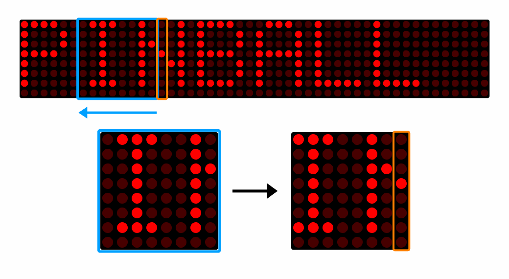
Our matrix sees only eight columns of that text (the blue frame). At each step the program moves all the dots one column to the left: the left column drops off the matrix, and the next column of the text comes in on the right (the orange frame). If this repeats quickly enough, the eye sees text scrolling to the left.
In the program it’s easier than it sounds. Each row of the matrix is one byte, and the bit on the far left is column C1. When we move all the bits of a byte one place to the left, the whole row moves. In the empty place on the right we write the dot from the next column of the letter.
The program
The program knows only the letters of the text PINBALL and the space. The letters’ pictures are in the two-dimensional array FONT, each on one line of the program, and the array CHARS says which picture is which letter: FONT[1] is the letter A, because CHARS[1] is 'A'. The send() and show() functions are the same as in the earlier exercises.
// C++
const int DIN = 2;              // data
const int CS = 3;               // frame of a message (LOAD on the chip)
const int CLK = 4;              // clock

const byte DECODE = 9;
const byte BRIGHTNESS = 10;
const byte ROW_COUNT = 11;
const byte POWER = 12;
const byte TEST = 15;

const char TEXT[] = "PINBALL ";             // the space at the end separates the end of the text from its start

// The characters the program knows and their pictures, in the same order.
// Each letter takes up the five left columns and the top seven rows.
const char CHARS[] = " ABILNP";
const byte FONT[][8] = {
  { B00000000, B00000000, B00000000, B00000000, B00000000, B00000000, B00000000, B00000000 },  // space
  { B01110000, B10001000, B10001000, B11111000, B10001000, B10001000, B10001000, B00000000 },  // A
  { B11110000, B10001000, B10001000, B11110000, B10001000, B10001000, B11110000, B00000000 },  // B
  { B01110000, B00100000, B00100000, B00100000, B00100000, B00100000, B01110000, B00000000 },  // I
  { B10000000, B10000000, B10000000, B10000000, B10000000, B10000000, B11111000, B00000000 },  // L
  { B10001000, B10001000, B11001000, B10101000, B10011000, B10001000, B10001000, B00000000 },  // N
  { B11110000, B10001000, B10001000, B11110000, B10000000, B10000000, B10000000, B00000000 },  // P
};

const byte WIDTH = 6;                       // columns per letter: five for the letter and one empty
const unsigned long INTERVAL = 80;          // ms between two steps

byte screen[8];                             // what is on the matrix now, row by row
byte letter = 0;                            // which letter of the text is coming in now
byte column = 0;                            // which column of that letter comes in next, 0 to 5
unsigned long lastStep = 0;                 // when the text last moved

void send(byte address, byte data) {
  digitalWrite(CS, LOW);
  shiftOut(DIN, CLK, MSBFIRST, address);
  shiftOut(DIN, CLK, MSBFIRST, data);
  digitalWrite(CS, HIGH);
}

void show(byte picture[8]) {
  for (byte r = 0; r < 8; r++) {
    send(r + 1, picture[r]);
  }
}

// Returns the place of a character in the CHARS array. A character that isn't there becomes a space.
byte charIndex(char c) {
  for (byte i = 0; i < strlen(CHARS); i++) {
    if (CHARS[i] == c) {
      return i;
    }
  }
  return 0;                                 // the space is first in the CHARS array
}

void setup() {
  pinMode(DIN, OUTPUT);
  pinMode(CS, OUTPUT);
  pinMode(CLK, OUTPUT);
  digitalWrite(CS, HIGH);

  send(TEST, 0);
  send(DECODE, 0);
  send(ROW_COUNT, 7);
  send(BRIGHTNESS, 1);
  for (byte row = 1; row <= 8; row++) {
    send(row, 0);
  }
  send(POWER, 1);
}

void loop() {
  if (millis() - lastStep >= INTERVAL) {
    lastStep = millis();
    byte f = charIndex(TEXT[letter]);       // which picture from the FONT array
    for (byte r = 0; r < 8; r++) {
      byte dot = bitRead(FONT[f][r], 7 - column);   // the dot in row r and in the letter's column
      screen[r] = (screen[r] << 1) | dot;   // the row moves one step left, and a new dot comes in on the right
    }
    show(screen);

    column++;                               // next time the next column comes in
    if (column == WIDTH) {                  // the whole letter has come in
      column = 0;
      letter++;
      if (letter == strlen(TEXT)) {         // the whole text has come in
        letter = 0;
      }
    }
  }
}
Upload the program. Does PINBALL scroll across the matrix from right to left, and then start again?
What’s new in the program?
const char TEXT[] = "PINBALL ";– Text in double quotes is an array of characters of typechar, one for each letter:TEXT[0]is'P', andTEXT[1]is'I'. The square brackets are empty because C++ counts how many places it needs by itself. The space at the end is an empty letter between the end of the text and its next start.strlen(TEXT)– A built-in function that returns how many characters the text has: 8, including the space (string length).const byte FONT[][8]– A two-dimensional array, likekeys[4][4]in the lesson on the switch matrix. Each row of the array is the picture of one character, eight bytes. A collection of pictures of letters is called a font.FONT[1][0]is the top row of the letter A.byte charIndex(char c)– Our own function that returns a value, likegetKey()in the lesson on the switch matrix. It goes through theCHARSarray and returns the place where it found the character. If the character isn’t there, it returns 0, so a space appears instead.bitRead(FONT[f][r], 7 - column)– The built-in functionbitRead(number, n)returns bitnof the number: 0 or 1. It counts the bits from the right, starting at zero, so the column on the far left is bit 7. That’s why we read the letter’s columncolumnas bit7 - column.screen[r] << 1– The<<sign moves all the bits one place to the left:B11000011 << 1stored in a byte isB10000110. The bit on the far left drops off, because a byte has only eight places, and a 0 comes in on the right.| dot– The|sign (or) sets the last bit to 1 ifdotis 1:B10000110 | 1isB10000111. Ifdotis 0, the byte stays the same. So the row moves one step to the left, and a new dot comes in on the right.byte screen[8];– What is on the matrix now, row by row. At the start the array holds only zeros, so the matrix is empty and the text comes into it from the right.columnandletter– They work like the hands of a clock:columncounts from 0 to 5, and when it reaches 6, it goes back to 0 andlettermoves on to the next letter. Whenletterhas gone through the whole text, it goes back to 0 too.
The text moves one column every 80 ms, so 12.5 columns a second. The whole of PINBALL with the space has 8 × 6 = 48 columns, so one pass takes about 3.8 seconds.
Try it:
- Set
INTERVALto 40, then to 200. Which text is easiest to read? - Write another word from the letters the program already knows, such as
"BALL ". - Write your name. Draw the letters that are missing in the character generator, in the five left columns and the top seven rows. Add the letter to the end of the
CHARSarray, and its eight bytes as a new line at the end of theFONTarray, so that both arrays are in the same order. The generator writes each byte on its own line, but in the program they can be on one.
Write in capital letters: to the program, 'a' is a different character from 'A'. Letters with accents, such as Č or é, don’t fit in one char, so the charIndex() function can’t find them. Instead, write a character you don’t otherwise use in the text and in the CHARS array, such as '#' for Č, and draw Č in its place in the FONT array.
What is B10110001 << 1 when we store it in a byte?
B01100010. All the bits move one place to the left, the first 1 on the left drops out of the byte, and a 0 comes in on the right.What happens when you write a letter in the text that isn't in the CHARS array?
charIndex() function doesn’t find it and returns 0, and FONT[0] is the space. Instead of that letter, six empty columns scroll across the matrix.Demonstration: a matrix without the chip (optional)
The instructor does this demonstration if there’s time left. It shows how much work the MAX7219 takes off the Arduino. Here the Arduino multiplexes the matrix by itself, without the chip, and a potentiometer chooses how many times a second it goes through all eight rows: from 5 times to as fast as it can.
Wiring
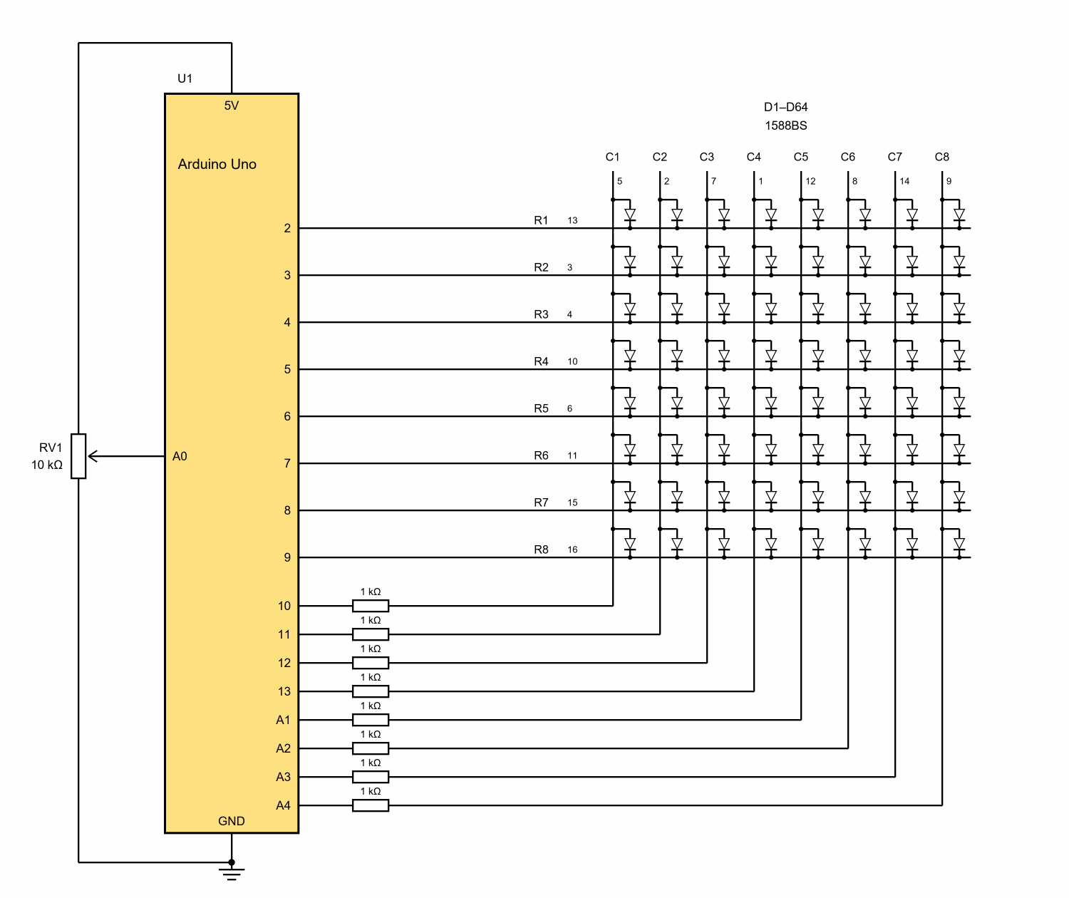
As in the module’s schematic, the row pins go straight across into the rows of the matrix, and the column pins through the resistors, under the matrix and up into the columns. In the drawing of the Arduino the pins aren’t in the same order as on the Arduino itself, but arranged so that no lines cross.
The rows of the matrix, its cathodes, are connected straight to pins D2 to D9. The columns, the anodes, are connected through 1 kΩ resistors to D10 to D13 and A1 to A4. The analog pins can work as ordinary digital outputs too. The wiper of the potentiometer is connected to A0, and its ends to 5V and GND, so the Arduino reads a number from 0 to 1023 on A0.
Each column has its own resistor, so about 2.5 mA flows through each LED that is lit, however many of them light in the row. The pin of the row that is switched on carries the current of all the LEDs in the row. When all eight light, that’s about 20 mA, and an Arduino pin shouldn’t carry more than that all the time. That’s why the resistors mustn’t be smaller than 1 kΩ, and the matrix can’t be any brighter. A brighter matrix would need eight more transistors, to carry the rows’ current instead of the pins.
| Row | R1 | R2 | R3 | R4 | R5 | R6 | R7 | R8 |
|---|---|---|---|---|---|---|---|---|
| Matrix pin | 13 | 3 | 4 | 10 | 6 | 11 | 15 | 16 |
| Arduino pin | D2 | D3 | D4 | D5 | D6 | D7 | D8 | D9 |
| Column | C1 | C2 | C3 | C4 | C5 | C6 | C7 | C8 |
|---|---|---|---|---|---|---|---|---|
| Matrix pin | 5 | 2 | 7 | 1 | 12 | 8 | 14 | 9 |
| Arduino pin, through 1 kΩ | D10 | D11 | D12 | D13 | A1 | A2 | A3 | A4 |
The matrix is turned a quarter turn clockwise from the drawing in the maker’s data: seen from the front, pins 1 to 8, on the side with the writing 1588BS, are on the left, with pin 1 at the top. Then its rows are its cathodes, as on the module, so a row is switched on with LOW and a column with HIGH, as with the MAX7219 chip, and the pictures from this lesson work unchanged. That’s why our rows are columns A to H in the maker’s data, and our columns are its rows 7 to 0.
How to build it is up to the instructor. Leave somewhere on rows R1 and R2 to hook the tip of an oscilloscope probe.
Without the chip or with it?
| Matrix without the chip | Module with the MAX7219 chip | |
|---|---|---|
| Arduino pins | 16 of the 18 free | 3 |
| Resistors | 8 | none (there’s one on the module) |
| Wires from the Arduino to the matrix | 16 | 5 |
| Current through an LED while it’s lit | about 2.5 mA | up to 40 mA |
| Who multiplexes | the program, all the time | the chip, by itself |
When does a matrix without the chip make sense?
When the microcontroller has enough pins, can multiplex in the background, and needs something the MAX7219 can't do. One example is the micro:bit. Its 25 LEDs have no chip of their own: they are wired straight to the pins of the microcontroller, which multiplexes them itself. At regular intervals the microcontroller pauses the program, switches the display to the next row and carries on with the program. This is called an interrupt. That's why a MakeCode program doesn't have to light row after row itself. The Arduino could do the same with an interrupt, but it would still need 16 pins.
- A brightness for each LED. The MAX7219 has one brightness for the whole matrix. The micro:bit can give each LED its own, because it decides itself how long each one is lit.
- LEDs as a light sensor. The micro:bit measures light with the LEDs of its display, because it can use their pins for a moment to measure as well. Through a chip it couldn't.
- Fewer parts. In a device that is made in large numbers, every chip left out is a saving.
Program
// C++
// A matrix without the MAX7219 chip: the Arduino lights row after row by itself.
// The potentiometer on A0 chooses how many times a second the program goes through all eight rows.

const int ROWS[8] = {2, 3, 4, 5, 6, 7, 8, 9};               // R1 to R8, cathodes
const int COLUMNS[8] = {10, 11, 12, 13, A1, A2, A3, A4};    // C1 to C8, anodes, each through 1 kΩ
const int POT = A0;
const int NOISE = 3;                // position jumps by this much even when the potentiometer is still

byte heart[8] = {
  B01100110,
  B11111111,
  B11111111,
  B11111111,
  B01111110,
  B00111100,
  B00011000,
  B00000000,
};

unsigned long frames = 0;           // how many times it went through all 8 rows this second
unsigned long lastCount = 0;        // when it last counted the frames
int printedPosition = -100;         // the position at the last print; -100: none yet
unsigned long printedFrames = 0;    // the last number of frames it printed

void setup() {
  for (int i = 0; i < 8; i++) {
    pinMode(ROWS[i], OUTPUT);
    digitalWrite(ROWS[i], HIGH);    // row off
    pinMode(COLUMNS[i], OUTPUT);
    digitalWrite(COLUMNS[i], LOW);  // column off
  }
  Serial.begin(9600);
}

void loop() {
  int position = analogRead(POT);
  unsigned long rowTime = 0;        // µs; 0: no waiting, as fast as it can
  if (position < 1000) {
    long framesPerSecond = map(position, 0, 999, 5, 100);
    rowTime = 1000000 / (framesPerSecond * 8);
  }

  for (int r = 0; r < 8; r++) {
    for (int c = 0; c < 8; c++) {   // the columns, while every row is off; bit 7 is C1
      digitalWrite(COLUMNS[c], bitRead(heart[r], 7 - c));
    }
    unsigned long start = micros();
    digitalWrite(ROWS[r], LOW);     // switch the row on
    while (micros() - start < rowTime) {
      // the row is lit
    }
    digitalWrite(ROWS[r], HIGH);    // switch the row off
  }

  frames++;
  if (millis() - lastCount >= 1000) {
    lastCount = millis();
    bool moved = abs(position - printedPosition) > NOISE;    // the potentiometer moved since the last print
    bool changed = frames != printedFrames;                  // or the number of frames is different
    if (moved || changed) {
      Serial.print("Frames per second: ");
      Serial.println(frames);
      printedPosition = position;
      printedFrames = frames;
    }
    frames = 0;
  }
}
What’s new in the program?
const int COLUMNS[8] = {10, 11, 12, 13, A1, A2, A3, A4};– The pins of the rows and columns are stored in arrays, so a loop can go through them in order.A1is just the name of a pin, like13.- The program first sets the columns, while every row is off, and only then switches the row on. If the row were switched on first, the pattern of the previous row would light in it for a moment, and faint ghosts would show on the matrix.
digitalWrite(COLUMNS[c], bitRead(heart[r], 7 - c));–bitRead()from Exercise 4 reads one bit of the picture’s row, 1 or 0, anddigitalWrite()sends it to the column’s pin. Bit 7 is column C1, as with the MAX7219 chip.map(position, 0, 999, 5, 100)– The potentiometer chooses from 5 to 100 frames per second. When it’s turned all the way andpositionis 1000 or more,rowTimestays 0, so the program doesn’t wait: it goes through the rows as fast as it can.while (micros() - start < rowTime)– A loop that waits while the row is lit. At 100 frames per second a row is lit for 1250 µs, anddelay()counts only whole milliseconds. So we wait withmicros(), as in the lesson about the ball.- Every second, the program counts how many times it went through all eight rows in that second. It prints that number to the Serial Monitor if the potentiometer has moved since the last print or if the number is different from the last one printed, so at most once a second. If two speeds get mixed in a second in which you turn the potentiometer, the next second’s number will be different, so the right number is printed too.
abs(position - printedPosition) > NOISE–abs()gives the number without its sign, so it doesn’t matter which way the potentiometer was turned. Even when the potentiometer is still,analogRead()gives slightly different numbers, for example 511 and then 513. So we don’t count a move of up toNOISEas a move.printedPositionstarts at -100, far from any position. So the first number is printed a second after the program starts.
Setting up the oscilloscope
The instructor measures how many frames a second the matrix really gets with the oscilloscope, as in the demonstration in Exercise 1. The Serial Monitor shows how many frames the program counted itself. The oscilloscope measures the voltage on the row pins, independently of the program, and also shows how long each row is lit. Here too, the ground clips go only on GND.
- Clip both ground clips onto GND. Then hook the tip of the CH1 probe onto row R1 (pin D2), and the tip of the CH2 probe onto row R2 (pin D3).
- The switch on the probe (1X or 10X) and the probe setting in the oscilloscope’s menu must be the same, for both channels. Set both channels to 2 V per division. Move CH1 into the top half of the screen and CH2 into the bottom half.
- Trigger: source CH1, falling edge, level about 2.5 V, mode Auto. A row is switched on with
LOW, so the oscilloscope triggers when R1 is switched on. - Switch on the frequency measurement (Freq) for CH1. R1 is switched on once in every frame, so its frequency is the number of frames per second.
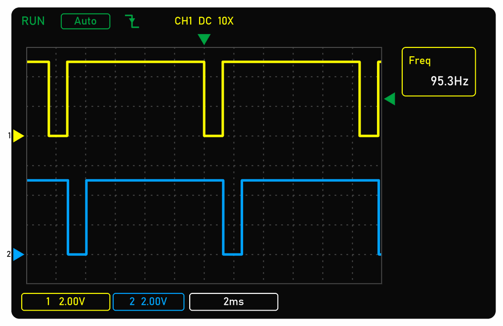
In the picture the potentiometer is set to 100 frames per second, and the time base is 2 ms per division. R1 is LOW for about 1.25 ms, an eighth of the time, and right after it R2 for just as long. From one pulse on CH1 to the next, one whole frame goes by. The oscilloscope shows a little less than 100 Hz, 95 Hz in the picture. Besides each wait, the program also spends time changing the pins and reading the potentiometer, and that isn’t in the calculation of rowTime. The Serial Monitor should show the same number.
What to show
- Open the Serial Monitor and turn the potentiometer until it shows 5 frames per second. Each row is lit for 25 ms, so you can see the rows of the heart light one at a time, from top to bottom. That’s multiplexing, slowed down so much that the eye can see it. On the oscilloscope, set the time base to 50 ms per division: R1 is
LOWfor 25 ms every 200 ms, and Freq is about 5 Hz. If the picture doesn’t stand still, choose the trigger mode Normal. - Turn the potentiometer slowly. At 10 to 20 frames per second the heart flickers badly. Somewhere around 50 to 60 frames per second the flicker disappears, although some people still see it a little above that out of the corner of their eye. Keep turning, almost all the way, until Freq shows about 95 Hz, and set the time base to 2 ms per division. The screen now looks like the picture above.
- Turn the potentiometer all the way. The program doesn’t wait any more and the Serial Monitor shows more than a thousand frames per second, but the heart is much darker. The Arduino now spends almost all its time changing the columns while every row is off, and each row is lit for only a few microseconds. On the oscilloscope, set the time base to 100 µs per division: Freq shows more than a thousand hertz, like the Serial Monitor, and the pulses on R1 and R2 are as thin as needles. At 2 µs per division you can see how short a pulse is: that’s all the time the row is lit. So faster isn’t always better: the picture has to be refreshed fast enough not to flicker, and each row has to be lit for most of its time.
- Turn the potentiometer back to about 100 frames per second. Add
delay(200);at the end ofloop(), as if the Arduino were doing something else, and upload the program. Now the heart blinks: while the Arduino waits, no row is lit. A matrix without the chip only lights while the Arduino multiplexes it.
The MAX7219 does the same as this program, about 800 times a second, but by itself, with its own circuits. So the Arduino keeps its pins and its time for other jobs, and in the pinball machine there are many: the flippers, the servos and the sound.
Why is the heart darker when the program doesn't wait between rows?
If something doesn’t work
- Nothing lights ⇒ Are VCC and GND on 5V and GND? Are the wires on the input header, the one marked DIN? Do DIN, CS and CLK go to D2, D3 and D4, in that order?
- Nothing lights, or the wrong LEDs light, but the wiring is right ⇒ The matrix is plugged into a socket on the module. Is it pushed all the way in? If it has been taken out and put back the wrong way round, turn it by half a turn.
- Every LED lights, and brightly ⇒ The chip is in test mode, because the messages arrive wrongly. Check that the DIN, CS and CLK wires are on the right pins and not swapped.
- Random LEDs light ⇒ The program doesn’t clear the rows before switching the chip on, or a wire is loose. Check the loop that clears the rows, and the wires.
- The picture is turned by 90° or upside down ⇒ Is the input header on the left, as in the picture under Wiring? If the header is at the bottom, towards you, the picture is turned by 90°. If the header is on the left and the picture still isn’t upright, the rows and columns of the matrix are wired differently on your module: turn the module until the picture is upright.
- The picture is mirrored, left is right, and the text in Exercise 4 scrolls to the right ⇒ On your module the columns are wired in the opposite order. In the
send()function, in the second call toshiftOut(), the one for the data, changeMSBFIRSTtoLSBFIRST. Then the data is sent lowest bit first. - Only some of the rows light ⇒ The number of rows must be 7.
- A letter is missing from the text ⇒ That character isn’t in the
CHARSarray, so the program shows it as a space. Is the letter written as a capital, as in theCHARSarray? - A different letter appears instead of one ⇒ The
CHARSandFONTarrays aren’t in the same order. A letter’s picture must be in the same place in theFONTarray as the letter in theCHARSarray. - The Arduino restarts, or the computer loses the USB connection ⇒ The matrix is using too much current. Lower the brightness.
- The program won’t upload ⇒ Check that the Arduino Uno board and the right port are selected in the Arduino IDE.
Extra challenges
- A dice. Connect a button to D7, as in the lesson on buttons. On each press, the matrix shows a random side of a dice, from one to six dots. Tip: store the six pictures in a two-dimensional array
byte dice[6][8], and get a random number from 0 to 5 withrandom(6). - An animation of several pictures. Draw three or four pictures in the generator that follow one another, such as a figure waving.
- The score. Add the digits 0 to 9 to the
CHARSandFONTarrays of Exercise 4, and make a score scroll across the matrix, such as"1250 ". The score on the pinball machine’s display will scroll the same way. - Breathing brightness. Make the brightness rise slowly from 0 to 15 and fall back to 0, without
delay().
 What did we learn?
- In an 8 × 8 LED matrix, the anodes in each column and the cathodes in each row are joined together, so 64 LEDs have only 16 pins.
- A row of the matrix is described by one byte: 1 is an LED that lights, and 0 one that doesn’t. The bit on the far left is column C1.
- Multiplexing: the rows light one at a time, so fast that the eye sees the whole picture.
- The MAX7219 chip multiplexes the matrix by itself, remembers the picture, limits the current and changes the brightness.
- The Arduino sends the chip messages of 16 bits over three wires: DIN for the data, CLK for the clock and CS as the frame of a message. The first 8 bits are a register’s address, and the second 8 the data.
- The built-in function
shiftOut()sends one byte bit by bit, andMSBFIRSTmeans that it sends the highest bit first. - The
bytetype stores a number from 0 to 255. We write a binary number in a program asB01100110. - Our own function can have several parameters, and a parameter can be an array.
- We draw a picture in the character generator and copy it as an array of eight bytes.
- An animation without
delay(): we change the picture whenmillis()says that enough time has passed, soloop()isn’t kept busy. - A text is an array of characters of type
char, andstrlen()returns how many characters it has. The pictures of the letters make up a font. - Scrolling text: we move each row one place to the left with
<<, and on the right we add, with|, the dot from the letter’s next column, which we read withbitRead().
Quick quiz
1. Why can't we light two rows with different patterns at the same time in a matrix?
2. What is multiplexing, and why doesn't the eye see it?
3. Which three wires connect the Arduino and the MAX7219, and what is each one for?
LOW while the message lasts, and when it goes back to HIGH, the chip writes the data into the register.4. How many bits does a message to the chip have, and what do they mean?
5. What does the call send(3, B11111111) do?
B11111111 into the register of row 3, so all eight LEDs in the third row light.6. Why does the program clear all eight rows at the start, before it switches the chip on?
7. Why doesn't loop() in Exercise 3 wait with delay()?
millis(), loop() only checks whether it’s time for a new picture and moves on straight away. In the pinball machine the same Uno drives the servos and the sound as well as the display.