
ATtiny85 and other small microcontrollers
The ATtiny85 and similar small microcontrollers: pins, memory, programming with an Uno in the Arduino IDE and PlatformIO, the Digispark, coin-cell power.
An Arduino Uno runs on one chip, the ATmega328P microcontroller. Everything else on the circuit board only helps it: a USB chip for the connection to the computer, a voltage regulator, a crystal for the clock, the RESET button and the LEDs. When a project is finished and needs only a few pins, a whole Uno is too big, draws too much current and is a waste to build in. Then you use the microcontroller on its own, without an Arduino around it. The best-known small microcontroller of this kind is the ATtiny85: it has only eight legs, it is smaller than a fingernail, and you program it in the same language and with the same commands as an Arduino.
This page is mostly about the ATtiny85 chip: how its pins are laid out, how an Arduino Uno uploads programs to it in the Arduino IDE and in PlatformIO, and how to make something with it that runs for months on a coin cell. At the end there are other small microcontrollers too, from the even smaller ATtiny13A to newer chips such as the ATtiny412 and the CH32V003.
The chip alone has none of the Uno's protection
There is no voltage regulator and no protection of any kind on the chip. The ATtiny85 works with 2.7 to 5.5 V: power it with 5 V from the Uno, from two or three AA batteries or from a 3 V coin cell. Never connect a 9 V battery to it directly. One pin may give at most 40 mA, and all the pins together about 60 mA. So count on 20 mA per pin, as on the Uno, and always connect an LED through a resistor.
A chip without an Arduino
The ATtiny85 comes in two cases. DIP-8 has its legs 2.54 mm apart, so it plugs into a breadboard across the middle gap, as in the picture further down. SOIC-8 is half the size, with legs 1.27 mm apart, and is soldered onto a circuit board. Inside they are the same.
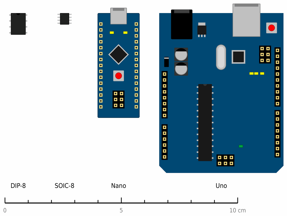
At one end of the chip there is a notch, and next to it a dot that marks leg 1. Seen from above, with the notch at the top, the legs are counted round the chip anticlockwise: down the left side from 1 to 4, then up the right side from 5 to 8. If you plug the chip in the wrong way round, plus and minus end up on the wrong legs and the chip can overheat.
To work, the chip needs only power: plus on leg 8 (VCC), minus on leg 4 (GND). On a board you build to keep, also put a 100 nF ceramic capacitor between those two legs, as close to the chip as you can. It gives the chip current at the moments when it suddenly needs a lot. You can’t upload a program to it over USB, because it has none. A programmer does that, and an Arduino Uno can be the programmer.
The ATtiny85 and the ATmega328P
The table puts the ATtiny85 next to the ATmega328P, the chip that runs on the Uno:
| ATtiny85 | ATmega328P (Uno) | |
|---|---|---|
| Legs | 8 | 28 (in a DIP case) |
| Input and output pins | 6 (5 while RESET stays RESET) | 23 (20 on the Uno) |
| Program memory (flash) | 8 KB | 32 KB |
| Working memory (RAM) | 512 B | 2 KB |
| EEPROM | 512 B | 1 KB |
| Analog inputs | 4 (one is on RESET) | 6 |
| PWM outputs | 3 | 6 |
| Serial connection (UART) | none, only in the program | yes |
| I2C and SPI | through one circuit (USI) | both |
| Clock | internal 1 or 8 MHz, 16 MHz with the PLL, crystal up to 20 MHz | 16 MHz with a crystal on the Uno |
| Voltage | 2.7 to 5.5 V (ATtiny85V from 1.8 V) | 1.8 to 5.5 V (Uno: 5 V) |
The numbers are from Microchip’s datasheets. The ATtiny85 has four times less program memory and working memory than the Uno, but for a program that switches LEDs, reads a button or a sensor and decides what to do next, that is enough. The Breathing program further down this page takes 532 bytes of 8192.
Pinout
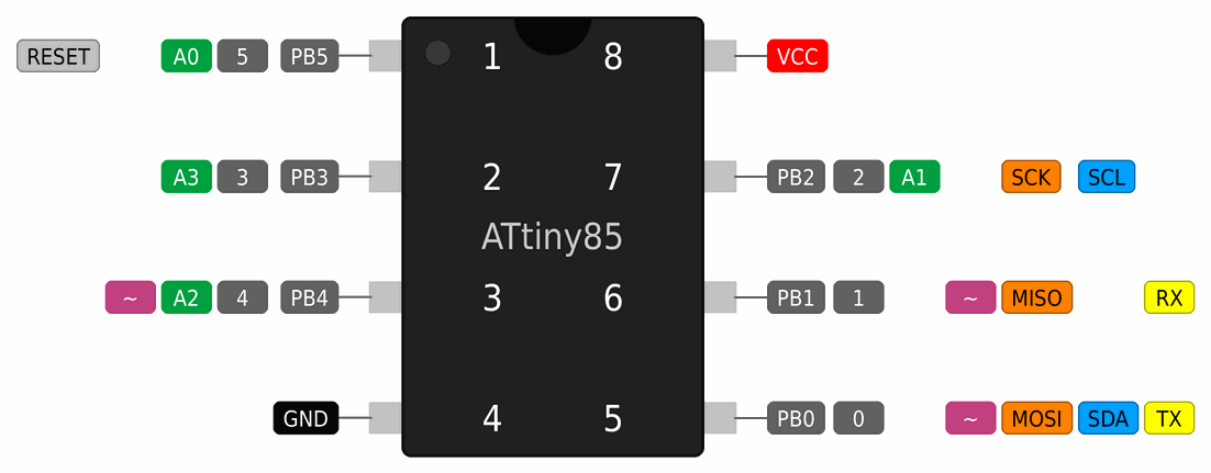
The labels in the picture have the same colours as on the Pinouts page.
| Label | What it means |
|---|---|
| VCC | power, 2.7 to 5.5 V |
| GND | minus, ground |
| PB4 4 | the pin’s name in the datasheet, then the pin number you write in the program |
| A2 | analog input |
| ~ | PWM output (analogWrite) |
| MOSI | the pins through which the programmer uploads the program (MOSI, MISO, SCK and RESET) |
| SDA | I2C connection (SDA and SCL) |
| TX | serial connection made by the program (TX and RX) |
| RESET | RESET |
What to watch out for:
- A leg and a pin don’t have the same number. The white number on the chip is the leg’s number. In the program you write the pin’s number, which is the number after the letters PB:
digitalWrite(4, HIGH)turns on pin PB4, and that is on leg 3. - The analog inputs are A1 (leg 7), A2 (leg 3) and A3 (leg 2). A0 is on leg 1, which is RESET: when the voltage on it drops too low, the chip resets. So in practice only three are left for measuring.
- PWM is on pins 0, 1 and 4. The
tone()command and the Servo library use the same timer (Timer1) as PWM on pin 4, so while they run,analogWrite()on pin 4 doesn’t work. - There is no serial port. The ATtiny85 has no UART circuit. So the ATTinyCore package has a
Serialmade in the program: it sends on pin 0 (TX) and receives on pin 1 (RX). To see it in the Serial Monitor you need a USB-to-serial adapter. The chip’s internal oscillator is only accurate to about 10 %, and a serial connection needs an accuracy of a few percent. If you see strange characters in the Serial Monitor, the clock is to blame. - I2C works with the Wire library on pins 0 (SDA) and 2 (SCL), but only with external pull-up resistors, for example 4.7 kΩ to plus.
- MOSI, MISO, SCK and RESET are used by the programmer. If something on them loads them heavily, programming can fail. An LED with a resistor doesn’t get in the way, but it is better to disconnect a module while you upload a program.
The clock and the fuse bits
The chip has a few settings that it remembers even without power. They are called fuse bits. They decide which clock the chip uses, whether leg 1 stays RESET and whether the EEPROM is kept when a new program is uploaded.
A new ATtiny85 runs at 1 MHz: the internal 8 MHz oscillator divided by 8. A program written for 8 MHz would run eight times slower on it, so delay(1000) would last eight seconds. So for every new chip you first set the fuse bits: in the Arduino IDE with the Burn Bootloader command, and in PlatformIO with pio run -t fuses. Do it again every time you change the clock.
The internal oscillator can run at 1 or 8 MHz, and with the PLL at 16 MHz. For a more accurate clock, up to 20 MHz, you need an external crystal, but it takes two legs (2 and 3).
Two settings after which the chip no longer answers
- An external crystal or external clock that you haven't connected. The chip then stands still waiting for a clock, so the programmer can no longer reach it. Connect the crystal or clock source you chose, then set the fuse bits again.
- RESET as a sixth ordinary pin (the RSTDISBL setting). Some instructions on the internet do this to get one more pin. After that the chip can no longer be programmed with an Uno, only with a special 12 V programmer (high-voltage).
Programming with an Uno
The ATtiny85 has no USB. A programmer uploads programs to it through four pins: MOSI, MISO, SCK and RESET. This way is called ISP (in-system programming), and it uses the same SPI connection as many modules. An Arduino Uno becomes a programmer when you upload the ArduinoISP program to it. The wiring is the same in the Arduino IDE and in PlatformIO.
The Uno becomes a programmer
- Connect the Uno, with nothing yet connected to pins 10 to 13, to the computer. In the Arduino IDE open File → Examples → 11.ArduinoISP → ArduinoISP, choose Arduino Uno and upload the program like any other. If you only work in PlatformIO, you’ll find the same program in Arduino’s arduino-examples repository on GitHub. Upload it in a project for the Uno.
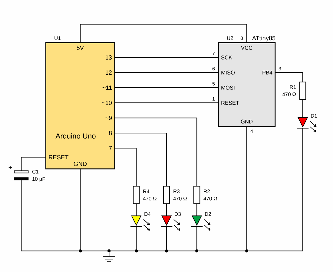
- Unplug the USB and connect the ATtiny85 as in the picture and the table. Make sure the chip’s notch is at the top.
- Between the Uno’s RESET and GND, plug in a 10 µF electrolytic capacitor, with its longer leg (+) on RESET. When the computer opens the connection to the Uno, the Uno normally resets and doesn’t start ArduinoISP in time. The capacitor prevents that. Put it in only after you have uploaded ArduinoISP, because with it not even the Uno can get a new program.
- Connect an LED to leg 3 (pin 4) through a 470 Ω resistor, for the first program.
| Uno | ATtiny85 |
|---|---|
| 13 | leg 7 (SCK) |
| 12 | leg 6 (MISO) |
| 11 | leg 5 (MOSI) |
| 10 | leg 1 (RESET) |
| 5V | leg 8 (VCC) |
| GND | leg 4 (GND) |
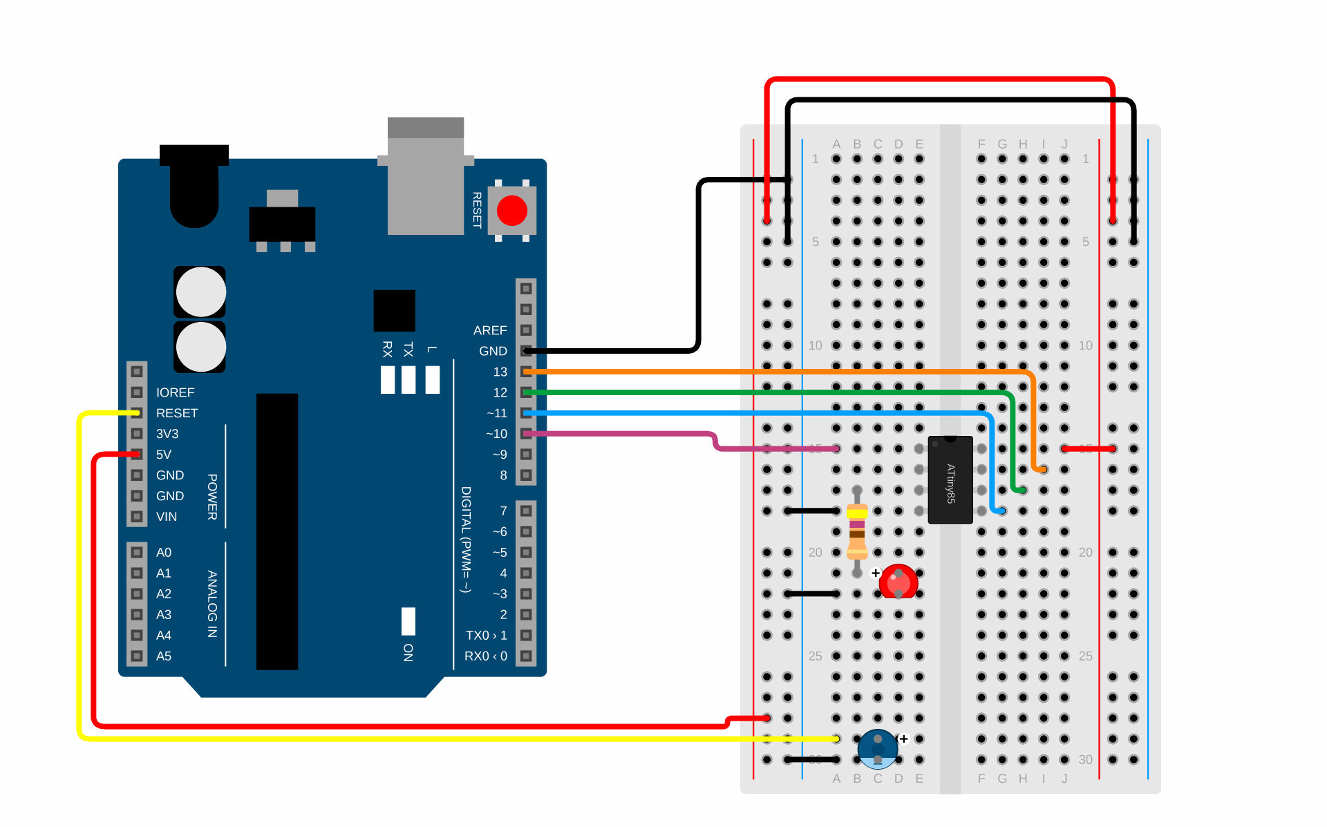
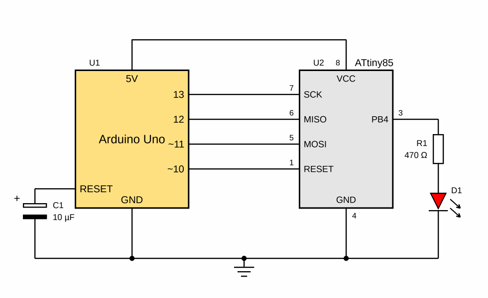
ArduinoISP can show what it is doing on three LEDs: the one on pin 9 slowly brightens and dims while it waits, the one on pin 8 lights when something fails, and the one on pin 7 while it uploads a program. They are optional.
The schematic shows the whole programmer with all three LEDs. Each LED has its own 470 Ω resistor to GND.
In the Arduino IDE
The Arduino IDE doesn’t know about the ATtiny85 on its own. It needs the ATTinyCore package.
- In File → Preferences, in the Additional boards manager URLs field, add the address
http://drazzy.com/package_drazzy.com_index.json. Then look for ATTinyCore in the Boards Manager and install it. - In the Tools menu choose:
- Board → ATTinyCore → ATtiny25/45/85 (No bootloader)
- Chip: ATtiny85
- Clock Source: 8 MHz (internal)
- Port: the Uno’s port
- Programmer: Arduino as ISP
- Choose Tools → Burn Bootloader. Despite its name, this doesn’t upload a bootloader, it only sets the fuse bits for the chosen clock. You do it once for every chip and after every change of Clock Source.
- Open the program and upload it with Sketch → Upload Using Programmer (Ctrl + Shift + U), which always uses the chosen programmer.
The first program: the LED on leg 3 slowly turns on and off, as if it were breathing.
// Breathing: the LED on pin 4 (leg 3) slowly turns on and off.
// ATtiny85, clock 8 MHz (internal); the program is uploaded by an Arduino Uno (Arduino as ISP).

const int LED = 4;   // PB4, leg 3

void setup() {
  pinMode(LED, OUTPUT);
}

void loop() {
  for (int i = 0; i <= 255; i++) {   // brighter and brighter
    analogWrite(LED, i);
    delay(4);
  }
  for (int i = 255; i >= 0; i--) {   // dimmer and dimmer
    analogWrite(LED, i);
    delay(4);
  }
}
If the upload fails and reports Device signature = 0x000000, the Uno can’t reach the chip. Check the wires against the table, that the chip’s notch is at the top, that the Uno has the capacitor on RESET and that the Uno is running ArduinoISP and not some other program.
In PlatformIO
PlatformIO uses the same ATTinyCore for the ATtiny85, so the programs look the same. Make a project for the Generic ATtiny85 board and write this in platformio.ini:
; An ATtiny85 programmed by an Arduino Uno running ArduinoISP
[env:attiny85]
platform = atmelavr
board = attiny85
framework = arduino
board_build.f_cpu = 8000000L      ; clock 8 MHz from the internal oscillator

; the Uno as the programmer (Arduino as ISP)
upload_protocol = stk500v1
upload_speed = 19200
upload_port = COM3                ; the Uno's port (on Linux e.g. /dev/ttyACM0)
upload_flags =
    -P$UPLOAD_PORT
    -b$UPLOAD_SPEED

; fuse bits for 8 MHz from the internal oscillator; "pio run -t fuses" sets them
board_fuses.lfuse = 0xE2
board_fuses.hfuse = 0xDF
board_fuses.efuse = 0xFF
board_fuses.lock_bits = 0xFF      ; the chip is not locked
upload_protocol = stk500v1andupload_speed = 19200say that the programmer is an Uno running ArduinoISP, which talks at 19,200 baud.upload_portis the Uno’s port. For the ATtiny85, PlatformIO doesn’t look for it on its own, so write it in: on Windows it is COM and a number (you can also see it in the Arduino IDE, in Tools → Port), and on Linux it is usually/dev/ttyACM0.upload_flagspasses the port and the speed to the program that uploads the program to the chip (avrdude).board_fusesare the fuse bits: 0xE2 is the 8 MHz clock from the internal oscillator, and 0xDF and 0xFF are the factory values of the other settings, with RESET staying RESET.
The program is in src/main.cpp and starts with #include <Arduino.h>; the rest is the same as above. Then:
- Once for every chip, and after every change of the clock, set the fuse bits. In PlatformIO’s terminal type
pio run -t fuses. - Upload the program like any other: with the Upload arrow in the bottom bar or with
pio run -t upload. PlatformIO then uses the Uno as the programmer by itself.
For a 1 MHz clock, change board_build.f_cpu to 1000000L and board_fuses.lfuse to 0x62, then set the fuse bits again.
The Digispark: an ATtiny85 with USB
The Digispark is a small circuit board with an ATtiny85 chip, a USB connector, a 5 V voltage regulator and an LED. The chip holds the Micronucleus bootloader, a small program that receives a new program over USB, so you don’t need an Uno as a programmer. The original Digispark was made by the company Digistump, and today mostly copies of it are sold.
- 6586 bytes are left for your program, because the bootloader takes the rest of the memory.
- The pins are called P0 to P5 and are the same as PB0 to PB5. P3 and P4 are connected to the USB. While the Digispark is connected to the computer, don’t use them, and keep in mind that there are extra parts for the USB on them.
- The LED is on P1 (on some copies on P0).
- When you plug it in, the bootloader waits a few seconds for a new program, and only then starts yours.
In the Arduino IDE, with ATTinyCore, choose Board → ATTinyCore → ATtiny85 (Micronucleus / DigiSpark) and click Upload. When the IDE writes Please plug in the device, plug the Digispark in within a minute. On Windows you first need to install a driver, which ATTinyCore brings with it.
A firefly on a coin cell
An Uno draws current even when it does nothing, because its USB chip, regulator and ON LED are always running. The ATtiny85 alone at 1 MHz and 3 V draws about 0.6 mA. When it sleeps (power-down), it draws only about 0.2 µA, and about 4 µA if it is woken by the watchdog, a small timer that keeps running while the chip sleeps. So you can make a device with it that runs for months on one coin cell.
The firefly: the LED flashes every four seconds, and the chip sleeps between the flashes. Connect it as above: the LED with a 470 Ω resistor on leg 3. Upload the program with the Uno with the clock set to 1 MHz (internal) (don’t forget Burn Bootloader). Then disconnect the Uno and connect a CR2032 holder to legs 8 (+) and 4 (−).
// Firefly: the LED on pin 4 flashes every 4 seconds, and the ATtiny85 sleeps between the flashes.
// ATtiny85, clock 1 MHz (internal), powered by a CR2032 coin cell.

#include <avr/sleep.h>

const int LED = 4;   // PB4, leg 3

ISR(WDT_vect) {
  // the watchdog has woken the chip up; nothing to do here
}

void setup() {
  pinMode(LED, OUTPUT);
  ADCSRA &= ~_BV(ADEN);                 // switch off the analog inputs, they draw current even in sleep
  WDTCR = _BV(WDCE) | _BV(WDE);         // allow changing the watchdog's settings
  WDTCR = _BV(WDIE) | _BV(WDP3);        // every 4 s an interrupt that wakes the chip (no reset)
  set_sleep_mode(SLEEP_MODE_PWR_DOWN);  // the deepest sleep
}

void loop() {
  digitalWrite(LED, HIGH);
  delay(50);
  digitalWrite(LED, LOW);
  sleep_mode();                         // sleep until the watchdog wakes you up
}
In setup() the program switches off the analog-to-digital converter, which would draw current even in sleep, and sets the watchdog to make an interrupt every four seconds. The interrupt wakes the chip, which runs the empty ISR(WDT_vect) and carries on after sleep_mode(), at the end of loop(). Then loop() starts again: a flash and sleep again.
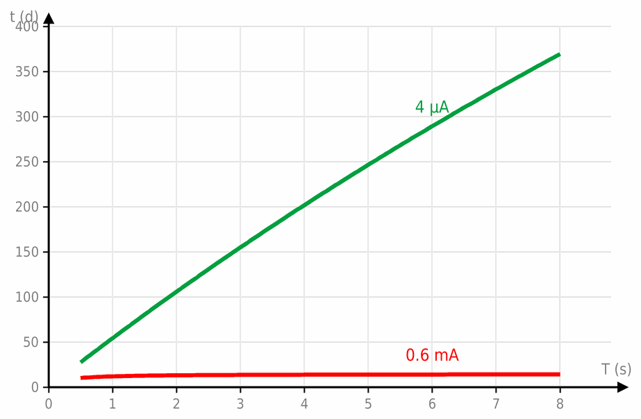
The graph is calculated from the datasheet’s currents: a 50 ms flash with an LED taking 2.6 mA, and a 210 mAh battery. If the program waited between the flashes with delay() instead of sleeping, the battery would last about 14 days, however many flashes there are (red). With sleep and a flash every four seconds it lasts about 200 days, and with a flash every eight seconds about 370 days (green). A real battery will give a little less, because it loses capacity in the cold and with strong short currents.
Never the battery and the Uno together
Don't connect the CR2032 while the Uno is connected to the chip. Current from the Uno's 5 V would flow into the battery, and lithium coin cells must not be charged: they can swell and leak. First upload the program, disconnect the Uno, and only then put the battery in. Keep coin cells away from small children.
Other small microcontrollers
The ATtiny85 isn’t the only small microcontroller. The table shows some others that can be programmed in the Arduino IDE, with the ATmega328P for comparison:
| Chip | Legs | Pins | Flash | RAM | UART | Programmed with | Arduino IDE package |
|---|---|---|---|---|---|---|---|
| ATtiny13A | 8 | 6 | 1 KB | 64 B | no | ISP | MicroCore |
| ATtiny85 | 8 | 6 | 8 KB | 512 B | no | ISP | ATTinyCore |
| ATtiny84A | 14 | 12 | 8 KB | 512 B | no | ISP | ATTinyCore |
| ATtiny2313A | 20 | 18 | 2 KB | 128 B | yes | ISP | ATTinyCore |
| ATtiny412 | 8 | 6 | 4 KB | 256 B | yes | UPDI | megaTinyCore |
| ATtiny1614 | 14 | 12 | 16 KB | 2 KB | yes | UPDI | megaTinyCore |
| CH32V003 | 8 to 20 | up to 18 | 16 KB | 2 KB | yes | SDI (WCH-LinkE) | WCH’s package |
| ATmega328P | 28 | 23 | 32 KB | 2 KB | yes | ISP | the same as for the Uno |
- The ATtiny13A has the same leg layout as the ATtiny85, but only 1 KB of program memory and 64 bytes of RAM. Only very small programs fit in that, such as blinking or a simple timer.
- The ATtiny84A is from the same family as the ATtiny85, but has 14 legs, 12 pins and 8 analog inputs. Choose it when the ATtiny85 runs out of pins.
- The ATtiny2313A (and the ATtiny4313, with twice the memory) has 20 legs and a real UART circuit, so a serial connection works reliably. It has no analog inputs.
- The newer ATtinys (series 0, 1 and 2), such as the ATtiny412 and the ATtiny1614, have UART, I2C and SPI circuits and an internal 16 or 20 MHz oscillator, accurate enough for a serial connection. They are programmed through one pin (UPDI), and the programmer is an ordinary USB-to-serial adapter with one diode. They only come in cases for soldering (SOIC), so for a breadboard you have to solder them onto a small board with a pin header.
- The CH32V003 from the Chinese company WCH has a 32-bit RISC-V core at 48 MHz, 16 KB of flash and 2 KB of RAM, and works with 3.3 or 5 V. It is programmed with the small WCH-LinkE programmer over one wire, and WCH has a package for the Arduino IDE.
- The ATmega328P can also work on its own on a breadboard, without an Uno. It needs a 16 MHz crystal or the internal 8 MHz oscillator, and the program is the same as on the Uno. It is a good choice when an ATtiny isn’t enough and a whole Uno is too much.
Microchip, the company that makes the ATtinys today, also makes small PIC microcontrollers, but they are programmed with other tools, not in the Arduino IDE.
Which one to choose?
- For learning and the first try: an Arduino Uno or Nano. When the program works, move it to a small chip.
- A small device with a few LEDs, a button or a sensor, on a battery: the ATtiny85. It plugs easily into a breadboard, and an Uno programs it.
- Without a programmer, over USB: the Digispark.
- More pins: the ATtiny84A, and when you also need more memory, an ATmega328P on its own on a breadboard.
- A serial connection to a computer or another chip: the ATtiny2313A or a newer ATtiny, such as the ATtiny412.
- Many identical devices on a circuit board you solder: the newer ATtinys or the CH32V003.
- Wi-Fi or Bluetooth: none of these, but an ESP32 or ESP8266.
 What did we learn?
- The ATtiny85 is a microcontroller with eight legs and six pins. It is programmed with the same commands as an Arduino, and apart from power it needs almost nothing.
- A leg and a pin don’t have the same number: in the program you write the number after the letters PB.
- With the ArduinoISP program an Uno becomes a programmer, in the Arduino IDE (Upload Using Programmer) and in PlatformIO (
upload_protocol = stk500v1). The Uno then needs a 10 µF capacitor on RESET. - The clock is set with the fuse bits, once for every chip: Burn Bootloader or
pio run -t fuses. - A sleeping chip draws a hundred times less current, so it runs for months on a coin cell.
Quick quiz
1. The LED is on leg 3 of an ATtiny85. Which number do you write in digitalWrite()?
- Leg 3 is pin PB4, and in the program you write the number after the letters PB:
digitalWrite(4, HIGH).
2. On a new chip, a program with delay(1000) blinks every eight seconds instead of every second. Why?
pio run -t fuses in PlatformIO.3. Why does an Uno that programs an ATtiny85 need a 10 µF capacitor between RESET and GND?
4. In the menu you chose 16 MHz (external), but there is no crystal. What happened, and how do you fix it?
5. A firefly that sleeps runs for about 200 days, and one that waits with delay() for about 14 days. Where does such a difference come from?
delay(), the chip runs and draws about 0.6 mA. While it sleeps, it draws about 4 µA, more than a hundred times less. The LED is on for only 50 ms every four seconds, so most of the current goes on what the chip does between the flashes.