Breadboard
How a breadboard works: which holes are connected, how to place components and wires, the power module, common mistakes and finding faults.
What is a breadboard?
A breadboard (a solderless prototyping board) is a plastic board full of holes into which we plug electronic components (resistors, LEDs, push buttons, chips, wires…) without soldering. We can quickly build a circuit, try it out, change it and take it apart, and use the components again later.
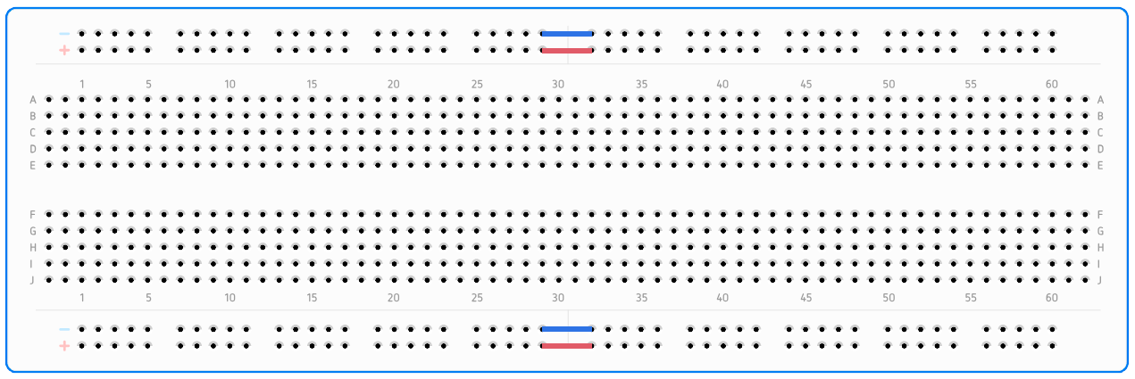
A breadboard is for a prototype, the first trial version of a circuit. When a circuit has to work reliably for a long time, we move it to a board for soldering (perfboard) or to a printed circuit board (PCB).
The rules for working safely with a breadboard are in the lessons Safety in the micro:bit workshop and Safety in the Arduino workshop.
How are the holes connected?
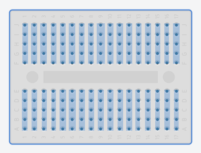
Under the holes there are metal strips with small clips. A clip grips a component leg or a wire firmly and connects it to all the other holes on the same strip. That is why components are connected as soon as you plug them in.
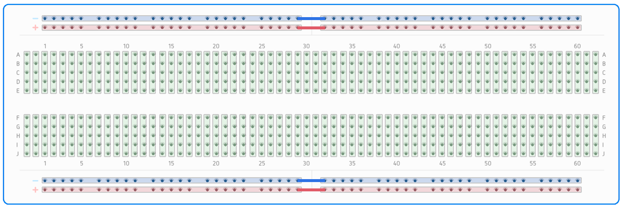
- Row: the five holes with the same number, on the same side of the middle gap (A–E or F–J), are connected to each other. In the picture the rows are vertical because the board is lying sideways; turn it and they are horizontal.
- The middle gap splits every row into two halves that are not connected: A–E and F–J. Push buttons and chips go across it.
- Power rails are the long lines along the edge of the board, marked + (red line) and – (blue or black line). All the holes in one rail are connected. We bring the plus and minus of the power supply into them, so they are close to every part of the circuit.
- A hole’s address is a letter and a number, like in the game Battleship: C13 is the hole in column C and row 13. With addresses it is easy to say where each leg goes.
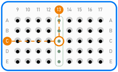
In the picture, hole C13 is in column C and row 13. The other four holes in the same row are marked green: they are connected to it.
The distance between neighbouring holes is 2.54 mm. That is the distance between the legs of most chips, modules and connectors, so they fit straight into a breadboard.
Rule to remember
Every connection point in a schematic becomes one row (or one power rail) on the breadboard. All the legs that are joined by a line in the schematic must end up in the same row or be connected with a wire.
Split power rails
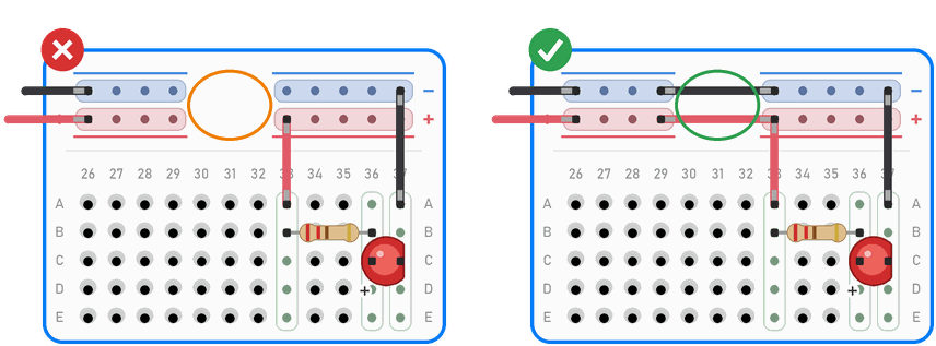
On many large breadboards the power rails are split in the middle of the board. You can usually see the split as a gap in the red and blue lines, but not on every board. If a circuit uses both halves of a rail, we bridge the split with short wires, as in the picture above (the red and blue wires at row 30).
The top and bottom power rails are not connected to each other either. If you need power on both sides of the board, connect them with wires: plus to plus, minus to minus.
When you are not sure whether something is connected, check it with a multimeter. In continuity mode the multimeter beeps when you touch two holes that are connected.
Breadboard sizes
- Mini (170 holes, 17 rows) has no power rails. We use it for small circuits in the micro:bit workshops.
- Half-size (about 400 holes, 30 rows) and
- Full-size (about 830 holes, 63 rows) have power rails. We use the full-size one in the Arduino workshops.
Breadboards have slots on their sides, so you can join them into a bigger board. The rows and power rails of two joined breadboards are not connected, and the holes don’t always line up.
On the bottom of the breadboard there is a sticky backing that holds the metal strips in place. We don’t peel it off: without it the clips can fall out.
How to place components
The most important rule: two legs of the same component never go into the same row. The row connects them, so the current flows through the metal strip and not through the component.
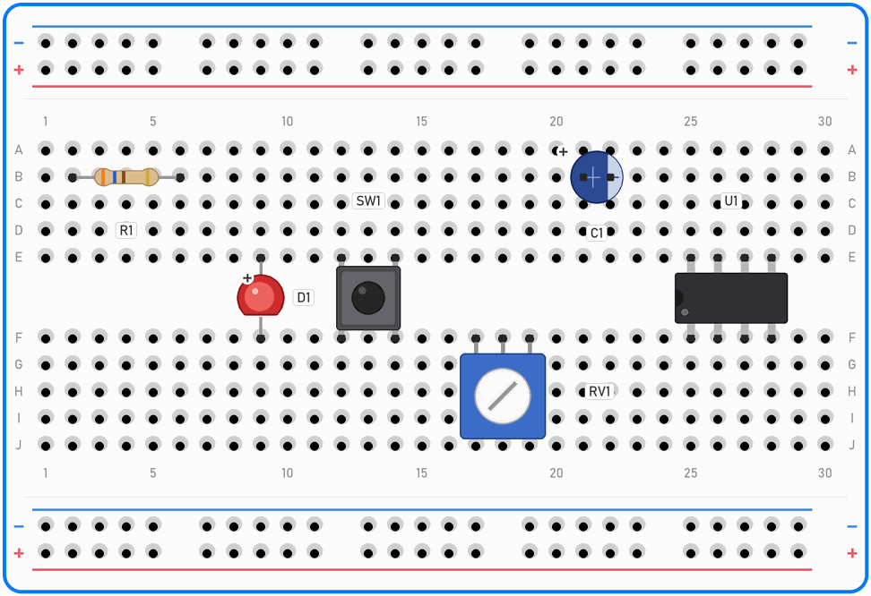
How to bend legs and wires
How deep? A leg or wire should go about 7 to 8 mm into the hole, roughly the thickness of a pencil. Only then does the metal clip grip it firmly. A shorter end only touches the top of the clip, so the connection works one moment and not the next. An end that is too long hits the bottom, bends and lifts the component.
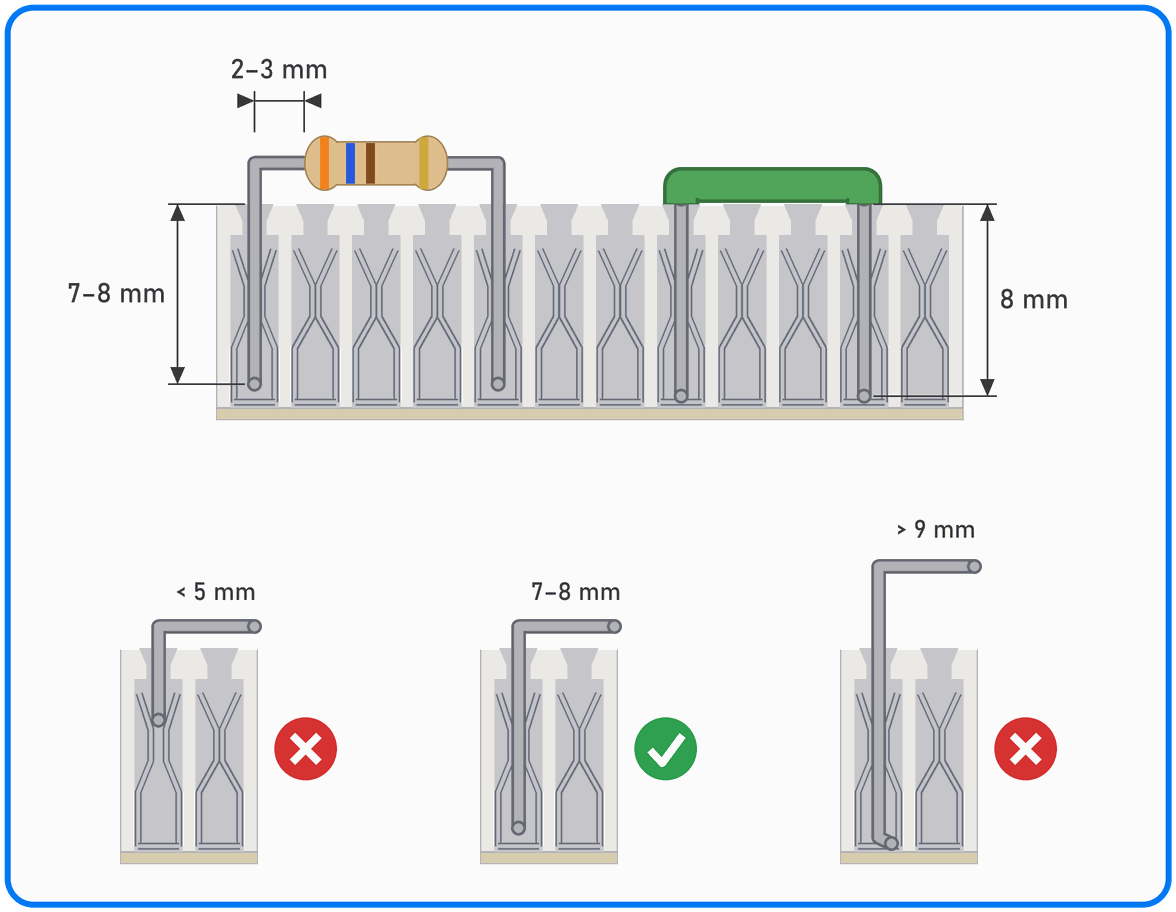
At the top is a cross-section of a breadboard with a resistor and a wire. Below are three legs: the one that is too short only touches the top of the clip, the right one is gripped firmly, and the one that is too long hits the bottom and lifts the component.
- Don't bend right at the body. Leave 2 to 3 mm of straight leg between the body of the component and the bend. A body that is bent right at its edge can crack, and an LED can stop working.
- Bend with pliers. Hold the leg with long-nose pliers right next to where you want the bend, and bend it around the tip of the pliers with your finger, to a right angle. This way the leg bends, not the point where it goes into the component.
- Measure before you bend. Hold the component above the board and bend the legs right above the holes they go into. When both legs are bent the same way, the component sits straight and low on the board.
- Don't bend the same spot twice. A leg that you bend back and forth in the same place soon breaks. If it is bent in the wrong place, make the new bend a little further along.
- Trimming: we only trim legs if the workshop leader agrees, because a component with long legs can be used again later. 7 to 8 mm must stay below the bend. On an LED, the longer leg (the anode) must still be the longer one after trimming. Hold the piece you cut off, or point it at the table, because a cut-off piece flies away and can hit someone's eye.
- Wires: strip about 8 mm of insulation from each end of the wire. If you strip less, the insulation goes into the hole and there is no connection; if you strip more, bare wire sticks out above the board and can touch the next wire. Bend the wire to a right angle exactly where the insulation ends, so it lies flat on the board. Cut the wire to the distance between the two holes, plus 2 × 8 mm for the ends.
- Pushing in: hold the leg close to the board, with your fingers or with pliers, and push it straight down. If it bends, hold it lower. If it still won't go in, don't force it; call the workshop leader.
Resistor
A resistor has no direction, so it doesn’t matter which way round it goes. Bend its legs to a right angle (see the box above), so that the resistor lies low on the board and spans three to five rows. Read the resistor’s value from its coloured bands (calculator).
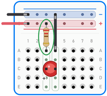
A resistor can also go straight from a power rail into a row, so you don’t need an extra wire. In the picture the resistor goes from the (+) rail straight into hole A3.
LED
An LED has a direction. The longer leg is the anode (+), the shorter one is the cathode (–), and the flat edge of the rim is on the cathode side. If the legs are the same length, look for the flat edge.
Put the legs in two different rows. An LED always needs a resistor in series; work out its value with the calculator.
Trick: if you spread the legs and put the LED across the middle gap, its legs are sure to be in different rows.
Push button
A small push button (6 × 6 mm) has four legs, which are connected in two pairs inside it. The legs of one pair are always connected, and pressing the button connects one pair to the other.
We put the push button across the middle gap. If its legs are in rows 7 and 9, pressing it connects row 7 to row 9. Press the button in straight until it sits all the way down. If a leg comes out to the side, take the button out, straighten the leg and try again.
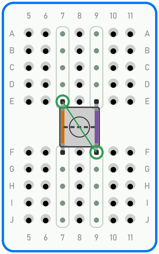
In the picture, the orange and purple lines show the pairs of legs that are always connected, and the dashed line shows the contact that closes when you press the button. The two diagonal legs are circled in green.
The diagonal trick
If you are not sure which legs of the push button are always connected, use two legs that are diagonally opposite each other (e.g. E7 and F9). They are always on different sides of the switch, whichever way the button is turned.
Potentiometer
A potentiometer has three legs, and each one goes into its own row. The middle leg is the wiper: its voltage changes when you turn the shaft. The outer legs go to plus and minus.
Some potentiometers have wide or thick legs that don’t fit into the holes. We don’t force them in; we use a potentiometer that fits a breadboard.
Electrolytic capacitor
An electrolytic capacitor has a polarity. The stripe with – signs on its side marks the minus leg, and the longer leg is plus. A capacitor that is the wrong way round can get hot, swell and burst. The voltage in the circuit must be lower than the voltage printed on the capacitor.
Small ceramic capacitors have no polarity and can go either way round.
Chip
A chip with two rows of legs goes across the middle gap. That is exactly what the gap is for: every leg gets its own row. A notch or dot on the chip marks the end where leg 1 is; turn all your chips the same way, e.g. with the notch to the left.
The legs of a new chip are spread a little. Before you plug it in, straighten them gently by pressing the chip sideways against the table. We take a chip out evenly from both ends, with a flat screwdriver or a chip puller; if you pull it out by one end, the legs at the other end bend.
Modules and boards with pins
Sensors and modules with pins 2.54 mm apart fit straight into a breadboard, each pin in its own row. If a module comes with its pins not soldered on, they have to be soldered first. Pins that are only pushed into the module make an unreliable connection: the circuit works one moment and not the next.
An Arduino Nano fits across the middle gap and leaves a few free holes on each side.
Some boards (e.g. an ESP32) are too wide for one breadboard and cover all the holes on one side. Trick: put two breadboards side by side and place the board across the join between them. On many breadboards you can remove a power rail, so the boards fit closer together.
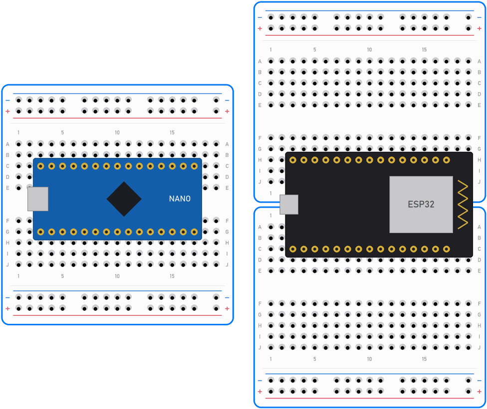
On the left, an Arduino Nano sits across the middle gap, with two or three free holes on each side. On the right, an ESP32 sits across two breadboards: the power rail between them has been removed, and two free holes are left on each side of the board.
Arduino Uno
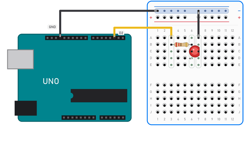
The Uno doesn’t sit on the breadboard; we connect it to the board with wires. The Arduino’s GND always goes to the (–) rail.
When the components are powered by the Arduino’s pins, the board doesn’t need 5 V (as in the lesson Traffic lights for cars and pedestrians). In the picture, pin D2 lights the LED, and only GND goes from the Arduino to the board.
When the circuit needs power, we connect 5 V to the (+) rail. In the picture, a potentiometer gets 5 V and GND, and its middle leg goes to pin A0.
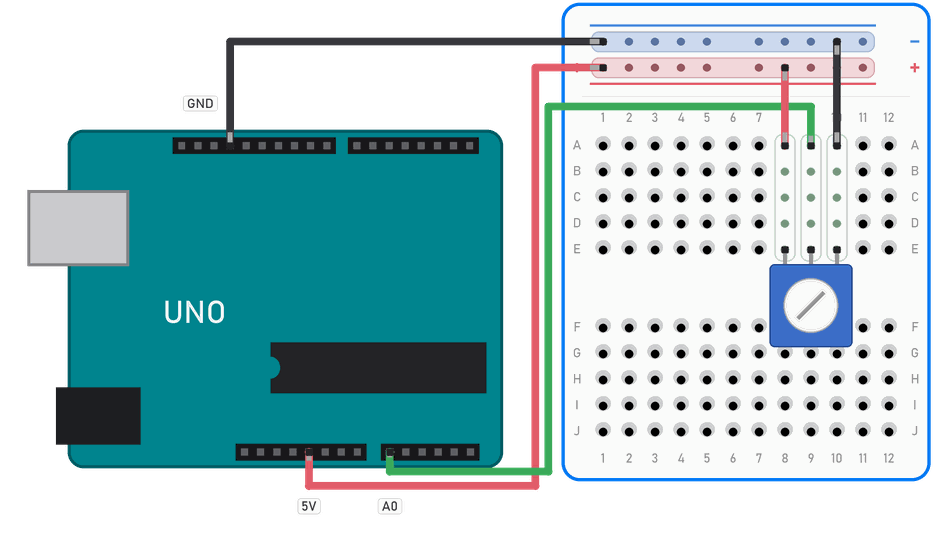
All parts of a circuit must share a common GND. An Arduino pin can safely supply up to about 20 mA.
micro:bit
We connect a micro:bit with crocodile clips: one end of the clip on a micro:bit pin, the other on a wire that is plugged into the breadboard. Make sure the clip doesn’t touch the small pins next to it on the edge of the micro:bit. For bigger circuits there is a micro:bit edge connector board that plugs straight into a breadboard.
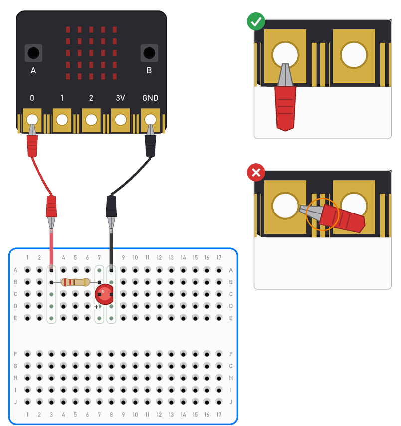
On the left, the red clip goes from pin 0 and the black one from GND. At the top right, the clip holds pin 0 well (✓). At the bottom it has slipped to the side, and its metal tip touches the small pins (✗).
A micro:bit works at 3.3 V and its pins supply only a small current, so here too an LED needs a resistor.
Power module
A circuit on a breadboard can also be powered from a power module. It is a small board that plugs into one end of the breadboard, into both pairs of power rails, and brings 5 V or 3.3 V into them. We power the module from a 9 V battery or a 12 V adapter.
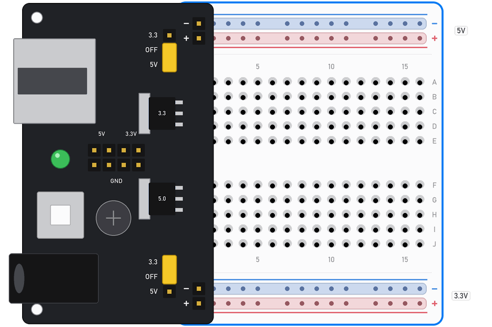
In the picture the top jumper is on 5V and the bottom one on 3.3, so the top power rails carry 5 V and the bottom ones 3.3 V. The power socket and the USB socket hang over the edge of the breadboard.
On the module there are:
- a power socket (round plug), an on/off switch and a green LED that lights up when the module is on;
- two voltage regulators, which turn the battery’s or adapter’s voltage into a steady 5 V and 3.3 V;
- a jumper on each side, which sets the voltage for that side of the board: 5V, OFF or 3.3. The two sides can have different voltages;
- pins marked 5V, 3.3V and GND in the middle of the module, for wires with pins on their ends;
- a USB socket, which supplies 5 V to another device. We don’t use it in the workshops.
Before switching on
- Check which way round it is: the + and – marks on the module must be next to the red (+) and blue (–) rails of the breadboard. The order of the rails is not the same on every board (see mistake 7 in Common mistakes).
- Set the jumper to the voltage the circuit needs, and the side you don’t use to OFF.
- Switch the module on and measure the voltage in the rails on both sides with a multimeter, before you plug in parts that the wrong voltage could damage.
Rules for the power module
- 3.3 V parts (e.g. the RC522 RFID reader) go only on the side where the jumper is on 3.3. 5 V damages them.
- Split rails: if the power rails are split in the middle of the board, the module only powers the half up to the split. Bridge the split with wires.
- Arduino on USB: we connect only the Arduino's GND to the module. We don't connect 5 V from the module to the 5V pin of an Arduino that is plugged into a computer: two 5 V sources push current into each other and into the computer.
- Not much current: the regulators turn the extra voltage into heat. With a 12 V adapter the module can supply about 100 mA, with a 9 V battery a little more. That is enough for LEDs, sensors, an RFID reader or one LED matrix at low brightness, but not for motors and servo motors. They need their own power supply.
- A hot module: if the module gets very hot or switches itself off, the circuit is drawing too much current or there is a short circuit somewhere. Switch off the power and call the workshop leader. Don't touch the regulators, they can burn you.
- A 12 V adapter: the module is made for 6.5 to 9 V. A 12 V adapter with nothing connected can give more than 15 V, which the regulator can't take. We only use adapters that the workshop leader has measured and labelled.
A 9 V battery runs down quickly. When the circuit starts behaving strangely or the LED on the module is dim, measure the battery: if it has less than about 7.5 V, replace it.
Tidy wiring
A tidy circuit is easier to check, and a mistake can be seen at a glance.
- Wire colours: red for plus, black (or blue) for minus (GND), other colours for signals. This way you can see at a glance where the power is.
- Short wires: a wire should be just long enough to reach where it goes and lie flat on the board. Long loops catch on fingers and cables, get pulled out and hide the rest of the circuit.
- Around, not over: we route wires around chips and components, not over them. This way a component can be taken out and the markings on it stay visible.
- All the same way round: turn all LEDs with the cathode to the same side, resistors so their colours read from left to right, and chips with the notch to the left.
- The right wire: what goes into the holes is wire with one solid core (solid wire). Wire made of many thin strands (stranded wire) splays out: strands stay in the hole or touch the next row. Stranded wire may only go into a hole if its end is tinned or has a metal pin.
- Leave space: leave a free row or two between the parts of a circuit, so fingers and multimeter probes can reach every leg.
- Build it step by step: first the power, then one part of the circuit. Test it, and only then add the next part. If something stops working, the mistake is in the last part.
- Tick the schematic: print the schematic and tick off each connection with a pencil as soon as you make it. When every line in the schematic is ticked, the circuit is finished.
Common mistakes
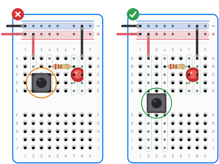
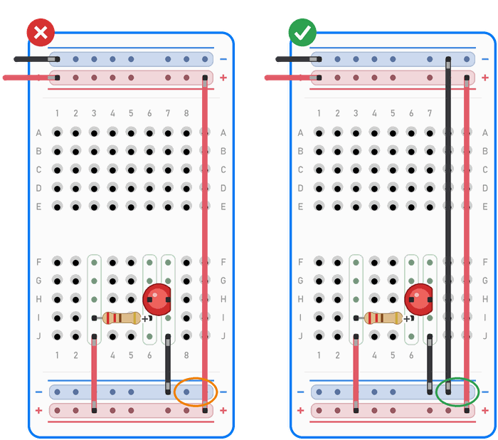
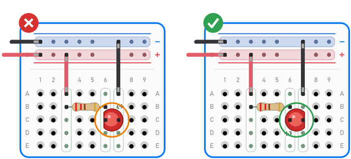
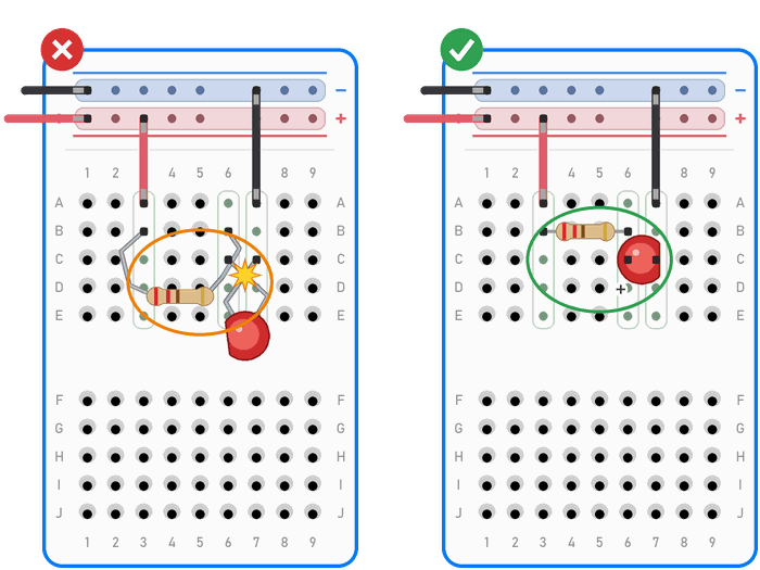
For each mistake, the left picture (✗) shows the mistake and the right one (✓) shows the correct circuit. An orange circle marks the mistake, and a green one the place where it has been fixed. Rows that are connected are marked green, and the power rails blue and red.
1. Both legs in the same row. The LED doesn’t light up, because the current flows through the metal strip in the row and not through the LED. The legs must be in two different rows.
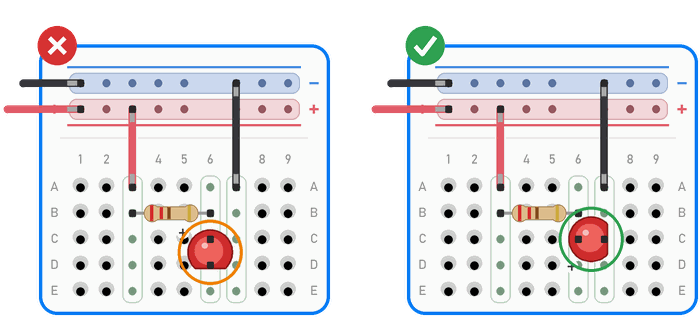
2. A leg in the next row. One leg has missed its row by one hole, so the resistor and the LED are not connected. Check the hole addresses.
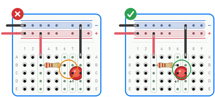
3. A split power rail. The circuit works on one half of the board but not on the other. Bridge the split with short wires: plus to plus, minus to minus.
4. A push button placed the wrong way. The LED is always on or never on. Put the push button across the middle gap and use the diagonal legs.
5. No common GND. In the picture the bottom (–) rail is not connected to the top one, so the minus doesn’t reach the LED. Connect plus to plus and minus to minus. The same happens when the Arduino and the rest of the circuit don’t have their GND connected: the circuit behaves strangely or doesn’t work.
6. An LED or capacitor the wrong way round. The LED doesn’t light up, and a capacitor can get hot. The longer leg of the LED (the anode) goes towards plus, and the flat edge of the rim towards minus.
7. Swapped rails. The red wire from the battery goes into the (+) rail, and the black one into the (–) rail. The order of the rails is not always the same at the top and the bottom, so always look at the colour of the line and the sign, not at where the rail is.
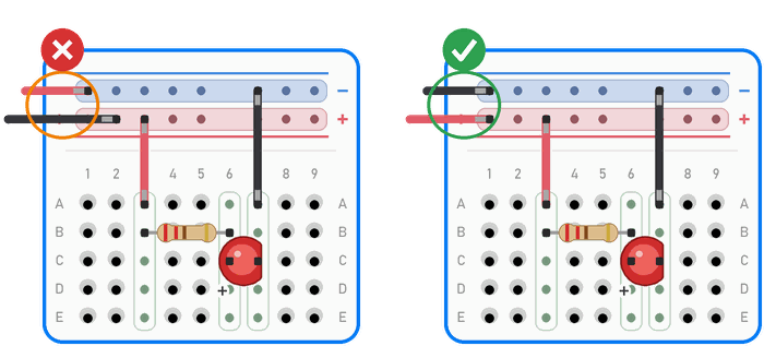
8. A wire connects plus straight to minus. That is a short circuit: the battery and the wire get hot. Switch off the power straight away and take that wire out.
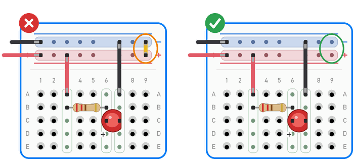
9. Legs that are too long and untidy. Long legs sticking out in all directions touch each other sooner or later, and that is a short circuit. In the picture the legs of the LED touch, so the LED doesn’t light up. If legs connected to plus and minus touch, the battery and the wires get hot. Bend the legs so that the component lies low on the board, and trim legs that are too long if the workshop leader agrees (see the box How to bend legs and wires in How to place components).
When the circuit doesn’t work
Don’t change everything at once; check things in order:
- Switch off the power.
- Look at the board from above and from the side, at eye level. Is every leg really in its hole, or is it bent under the component or next to the hole?
- Take the schematic and, for every connection in it, find the same connection on the board with your finger.
- Check which way round the LEDs, capacitors and chips are, and check the legs of the push button.
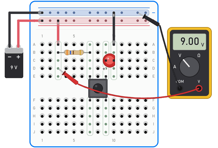
- If you have a multimeter: with the power off, check the connections (continuity beep). Then switch the power on and measure the voltage, first on the power rails and then on the legs of the components. The black probe is on GND; put the red one into a free hole in the same row as the leg. In the picture the red probe is in D3, in the same row as the resistor, so the multimeter shows the battery voltage.
- Swap the wire. Wires with pins on their ends often break inside, under the insulation, while they look fine from the outside.
- Move the component to other holes. A hole into which someone has pushed a thick leg no longer grips well.
- Replace a component you suspect (e.g. an LED) with one you know works.
- If the circuit still doesn’t work, split it into two parts and check each part separately.
What we don’t do on a breadboard
A breadboard isn't for everything
- We never connect mains voltage (230 V from a wall socket) or anything that is plugged into a socket.
- We don't run large currents. On a breadboard we don't work with currents above about 1 A. Motors and bright LED strips need their own power supply and thicker wires.
- We don't power motors and servo motors from an Arduino pin or from the power module.
- We don't force thick legs into the holes (e.g. 1N4007 diodes or a power connector). They stretch the clip for good, and then that hole no longer holds thin legs.
- If a component gets very hot, we switch off the power straight away. A hot resistor can melt the plastic, and it usually means a wrong value or a mistake in the wiring.
- A breadboard is not for devices that shake or fly (e.g. a drone), because the components fall out. We solder circuits like that.
Tricks
- A shared base: fix the Arduino Uno and the breadboard to the same board or a 3D-printed holder. When someone pulls the USB cable, the wires stay in place.
- Labels on the rails: a piece of tape with a label (+5 V, GND, 9 V) shows which voltage is in which rail.
- A photo: when the circuit works, take a photo of it. If something gets pulled out or you have to take it apart, you know how it was wired.
- A plan on paper: before wiring, draw the layout on squared paper, with the row numbers and column letters.
- An LED as a tester: an LED with a resistor, connected between a row and the (–) rail, shows whether there is voltage in that row. Mind which way round the LED goes. In the picture the LED lights up, because the red wire brings plus into row 2.
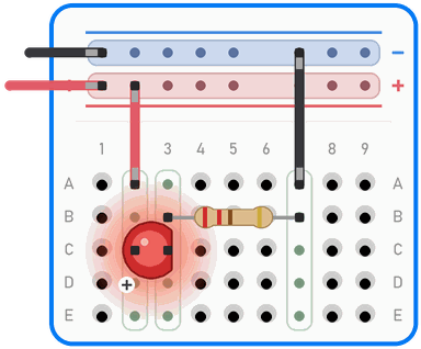
Example: from schematic to breadboard
We will build an LED that lights up while we hold down a push button, powered by a 9 V battery.
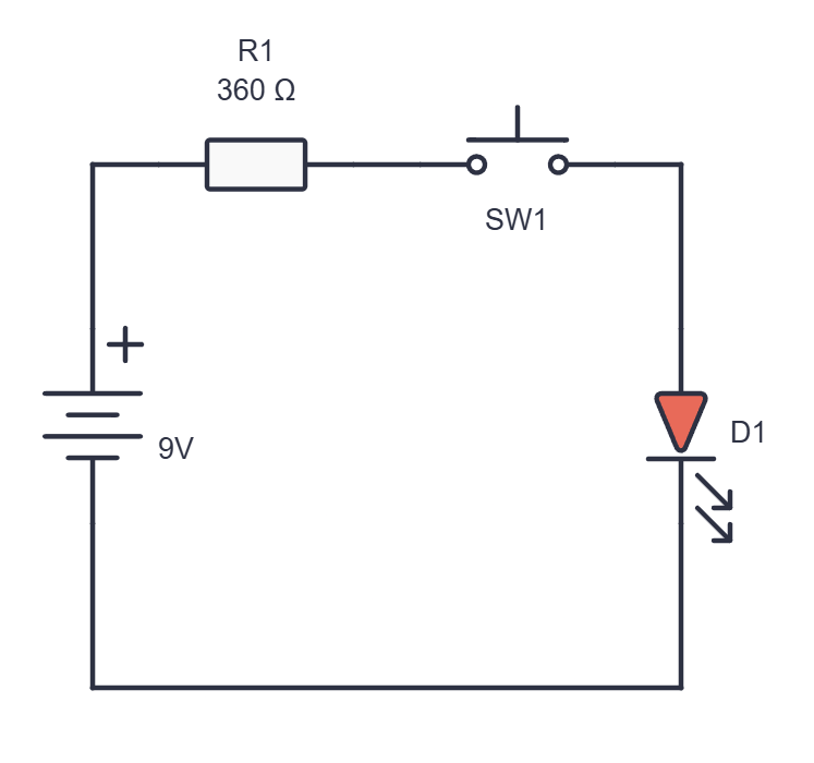
The 360 Ω resistor (orange-blue-brown) limits the current through the LED to about 19 mA.
How do we connect it?
- Check that the battery is disconnected.
- With a red wire, connect the top (+) rail to hole A3.
- Put the resistor into holes B3 and B7.
- Put the push button across the middle gap, with its legs in E7, E9, F7 and F9.
- Put the longer leg of the LED (the anode) into C9 and the shorter one (the cathode) into C10.
- With a black wire, connect A10 to the top (–) rail.
- Compare the circuit with the schematic: plus ⇒ resistor ⇒ push button ⇒ LED ⇒ minus.
- Connect the plus of the battery to the top (+) rail and the minus to the top (–) rail. Press the push button.

The rows the circuit uses are marked green, and the power rails blue and red.
If the LED doesn’t light up, go through the checklist.
 What did we learn?
- Under the holes of a breadboard there are metal strips: the five holes in a row (A–E or F–J) are connected, and the middle gap splits a row into two halves that are not connected.
- The power rails along the edge carry plus and minus along the board, but on large breadboards they can be split in the middle.
- Two legs of the same component never go into the same row.
- Push buttons and chips go across the middle gap.
- A power module supplies 5 V or 3.3 V to each side of the board. Before switching on, we check which way round it is, the jumpers and the voltage, and with the Arduino on USB we connect only GND.
- A tidy circuit (wire colours, short wires, building step by step) is easier to check and fix.
- When a circuit doesn’t work, we check in order: power off, a look at the board, the connections from the schematic, which way round the components are, the multimeter, the wires.
Short quiz
1. Why doesn't an LED light up if both its legs are in the same row?
2. Are holes C13 and H13 connected?
3. A circuit works on the left half of a large breadboard but not on the right half. What is the most likely cause?
4. Why do we put push buttons and chips across the middle gap?
5. What do you do before you move a wire or a component?
6. A power module is plugged into the left end of a large breadboard. An LED on the right half of the board doesn't light up. What do you check?
7. The Arduino is plugged into a computer, and the rest of the circuit is powered by a power module. Which of the Arduino's power pins do we connect to the circuit?