
Buttons and switches
Push buttons, microswitches, tilt and reed switches: how they work, wiring them to an Arduino with a pull-up resistor, and why contacts bounce.
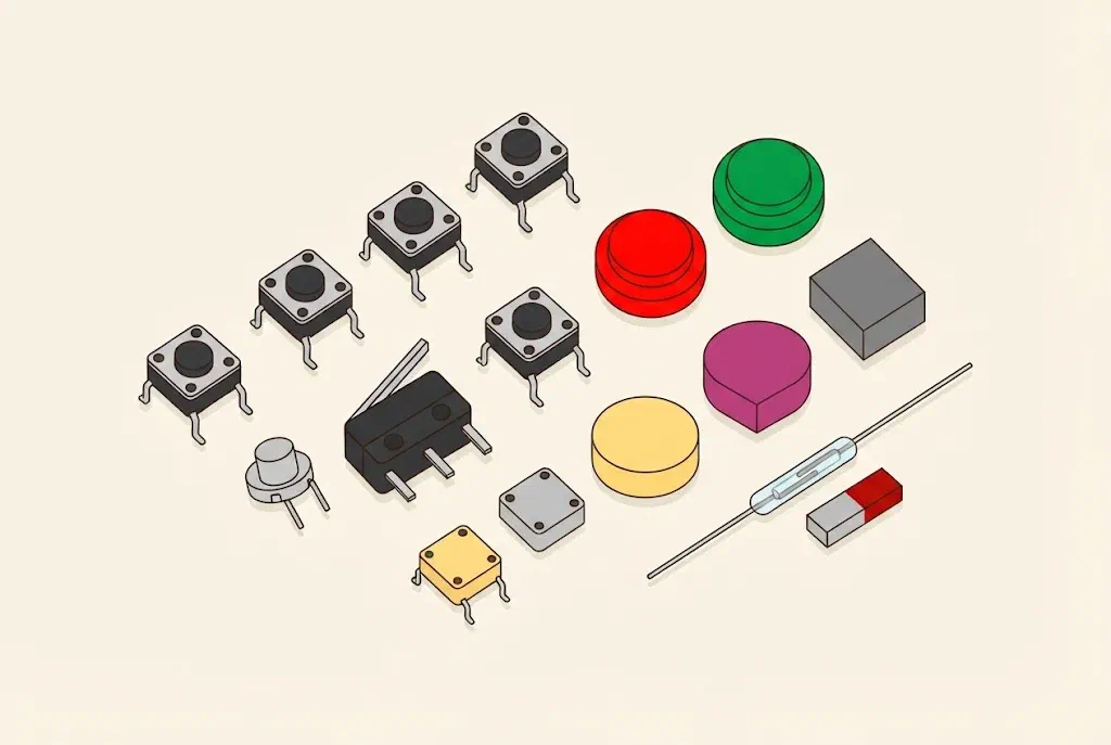
What are buttons and switches?
A push button and a switch do the same job: they join and separate two pieces of metal, the contacts. When the contacts touch, current flows. When they are apart, it doesn’t. The difference is what happens when you let go:
- A push button joins the contacts only while you hold it. When you let go, a spring pushes it back. The button of a doorbell, the keys on a keyboard and buttons A and B on the micro:bit are push buttons.
- A switch stays the way you set it until you move it again. The light switch in your room and the switch that turns on the Maqueen robot are switches.
Some switches are not moved by a hand but by something else: a ball hitting a lever, a tilt or a magnet. Such switches are the simplest sensors.
How to recognise them
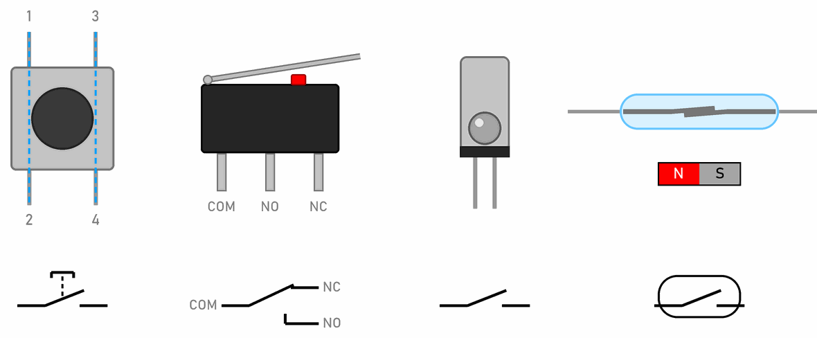
- A small push button (6 × 6 mm) has four legs but only two contacts. Legs 1 and 2 are joined inside, and so are legs 3 and 4. Pressing joins the pair 1 and 2 to the pair 3 and 4. That is why the button goes across the middle groove of the breadboard, as on the Breadboard page. If you aren’t sure which legs are joined, check with a multimeter.
- A microswitch is a small push button with a lever. It needs very little force, and its contacts snap over with a quiet click. It has three legs:
- COM (common) is the leg that is always used,
- NO (normally open) is joined to COM while the lever is pressed,
- NC (normally closed) is joined to COM while the lever is not pressed.
- A ball tilt switch (tilt sensor) is a small metal can with a ball inside. While it stands upright, the ball lies at the bottom and joins the contacts. When you tilt or shake it, the ball rolls away and the contacts separate.
- A reed switch is two thin metal strips in a glass tube. When you bring a magnet near, the strips are pulled together and touch. The glass is thin: don’t bend the legs right next to the tube, but a little further away.
Below each part is its symbol. On the push button’s symbol, the stem with a button on top says that a hand holds the contact. The reed switch has the outline of its glass tube.
What is inside a push button?
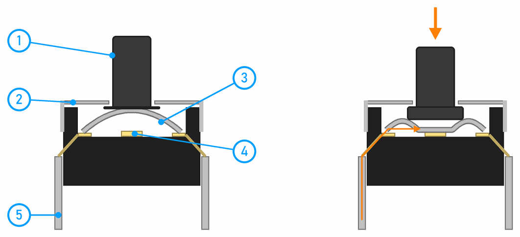
- The button is the plastic knob you press with your finger.
- The metal cover holds all the parts together.
- The metal dome is a thin curved plate. When you press it, it snaps down with a click, and when you let go, it springs back by itself. It is the spring as well.
- The contacts: the rim of the dome always rests on the outer contacts, and it touches the middle contact only while it is pressed.
- The legs are joined to the contacts. The outer contact goes to one pair of legs, the middle one to the other.
On the right the button is pressed. The dome has snapped down and touches the middle contact, so current flows from one pair of legs through the dome to the other.
Where we use them
- At the micro:bit workshop, a push button closes the circuit in the Breadboard lab. In the lesson Switches and the bumper we try out a push button, a microswitch and a tilt switch, and a microswitch becomes the bumper of the Maqueen robot.
- At the Arduino workshop we read buttons in Buttons done right, and many of them on a few pins in Many switches on few pins. In Detecting the ball a microswitch counts the ball’s hits, and a ball tilt switch checks that the player doesn’t push the machine.
- In our pinball machine buttons work the flippers and start the game, microswitches sit under the targets, and four ball tilt switches make up the tilt.
Buttons and switches at the Arduino workshop
From here on, this page is for the Arduino workshop.
A pin must not float
While the button isn’t pressed, the pin it is connected to isn’t connected to anything. Such a floating pin reads 0 or 1 at random (misconception 10). So the pin is always also connected through a resistor, which holds it in a known state while the button is at rest.
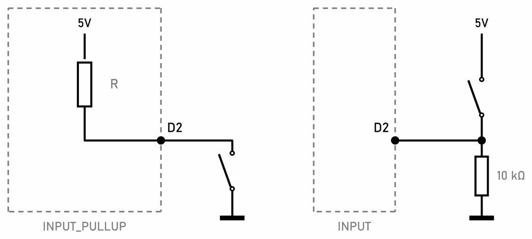
- A pull-up resistor (left) connects the pin to 5 V. A released button gives
HIGH, and a pressed one connects the pin to GND and givesLOW. The Arduino Uno has such a resistor built in, 20 to 50 kΩ.pinMode(pin, INPUT_PULLUP)turns it on, so nothing but the button goes on the breadboard. - A pull-down resistor (right) connects the pin to GND, and the button goes to 5 V. A pressed button gives
HIGH. The Uno has no built-in pull-down resistors, so we add a 10 kΩ one, as in Two traffic lights at a crossroads.
We wire buttons with a pull-up resistor: it takes fewer parts, and we don’t need 5 V on the breadboard. While the button is pressed, only about 0.14 mA flows through the built-in resistor. How the program reads the button is in Exercise 1 of the lesson on buttons.
Contact bounce
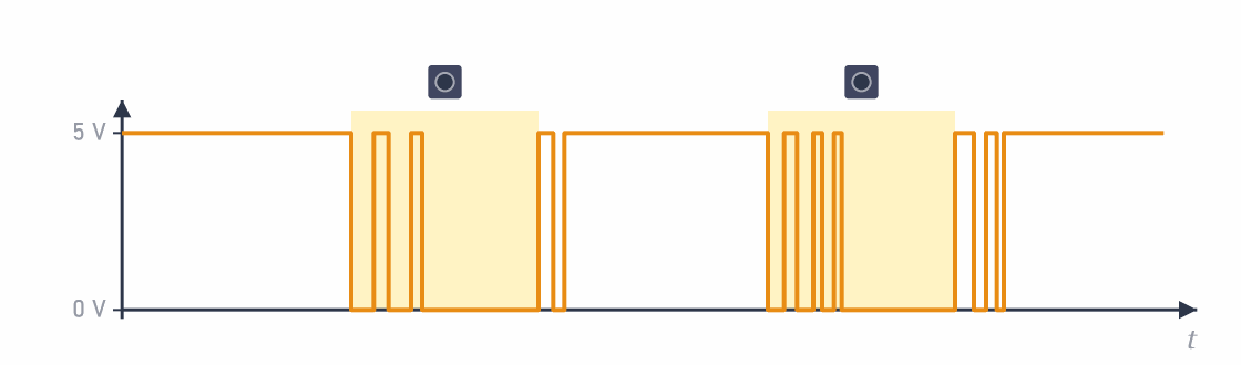
When the metal contacts hit each other, they bounce, like a ball dropped on the floor, and settle only after a few milliseconds. The same happens when you let go. A person can’t notice it, but the Arduino reads the button many times every millisecond and sees every bounce:
Debouncing with a capacitor
Contacts can also be debounced without a program: with a 100 nF capacitor (code 104) straight across the button’s legs. The graph shows the voltage on pin D2 during one press and release, with the built-in pull-up resistor. The bounces are an example. In the yellow part the button is pressed, and the dashed lines are the limits of 3 V and 1.5 V: above 3 V the Uno surely reads 1, and below 1.5 V it surely reads 0.
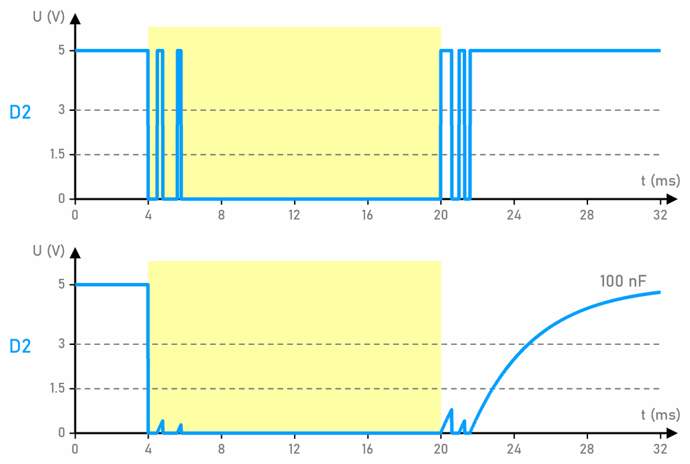
- The press: the first touch of the contacts empties the capacitor at once. While the contacts bounce, the pull-up resistor charges it, but slowly: in a 0.3 ms gap the voltage rises only to 0.4 V, far below 1.5 V. The Arduino sees one clean press.
- The release: every new touch empties the capacitor again. The voltage starts to rise only when the contacts settle, and it passes 3 V 3.2 ms after the last bounce.
How fast it charges is set by the time constant τ = R · C = 35 kΩ · 100 nF = 3.5 ms (how a capacitor charges is explained on the Capacitor page). The built-in resistor can be anything from 20 to 50 kΩ, so τ is 2 to 5 ms. That is fine for buttons, but the release always comes a few milliseconds late. At the workshop we therefore debounce in the program, where we choose the time ourselves.
NO or NC?
A microswitch can be wired with its legs COM and NO, or COM and NC. The program can read either, but they differ when something goes wrong. If the wire to a microswitch wired to NO breaks, the Arduino thinks nobody is pressing it, and nobody notices. With NC a broken wire looks like a press that never ends, so you see it at once. That is why the tilt in Detecting the ball treats a broken wire as a switch that has been open for too long.
So switches that guard something important, such as the one on a washing machine’s door or at the end of a machine’s travel, are wired so that a broken wire stops the machine.
Many buttons on a few pins
The Uno has only 18 free pins, and in the pinball machine the display, the lights and the sound need pins as well as the switches. So the buttons go into a matrix of rows and columns, so that 12 keys need only 7 pins. How the matrix works and why it needs diodes is explained in Many switches on few pins.
How much current can the contacts take?
Contacts wear, and a stronger current wears them faster: a small spark jumps between them as they separate. Rough values for parts like ours:
| Part | Highest current through the contacts |
|---|---|
| 6 × 6 mm push button | about 50 mA at 12 V |
| reed switch | about 0.5 A, but less when the load is a coil |
| microswitch with a lever | a few amps |
The real values are in each part’s datasheet. So a push button or a reed switch only tells the Arduino that something has been pressed. A motor, a coil or a bright bulb is switched by a transistor, not by the button’s contacts.
 What did we learn?
- A push button joins the contacts only while you hold it, and a switch stays the way you set it.
- A small push button has four legs: 1 and 2, and 3 and 4, are joined inside. A microswitch has COM, NO and NC.
- A pin with a button needs a pull-up or pull-down resistor. With
INPUT_PULLUPa pressed button givesLOW. - Contacts bounce for a few milliseconds. We debounce them in the program or with a capacitor.
- A contact wired to NC also reports a broken wire. A button only reports, and strong currents are switched by a transistor.
Quick quiz
1. What is the difference between a push button and a switch?
2. A small push button has four legs. Why does it go across the middle groove of the breadboard?
3. A microswitch is wired with its legs COM and NC. When are the contacts joined?
4. A button is wired between D2 and GND, with INPUT_PULLUP. What does digitalRead(2) give while it is pressed?
LOW. A pressed button connects the pin to GND, and while it is released the built-in pull-up resistor holds the pin HIGH.5. Why does a program without debouncing count one press as several?
6. Why don't we switch a motor straight with a 6 × 6 mm push button?