
Capacitor
How a capacitor stores charge: ceramic and electrolytic, polarity, charging through a resistor, the time constant, the code 104 and what capacitors are for.
What is a capacitor?
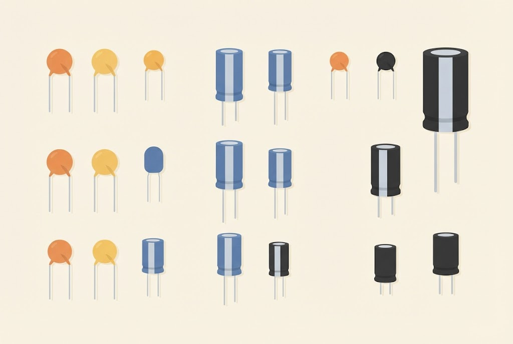
A capacitor is a component that can store a little electric charge and then give it back. Think of a small bucket of water: the current fills it, and when needed, the water flows back out of it. A capacitor fills and empties very fast, but it holds much less energy than a battery.
Inside there are two metal plates with a thin insulator between them. Current doesn’t flow through the insulator; instead, charge collects on the plates: plus on one, minus on the other.
The capacitance, how much charge a capacitor can store, is measured in farads (F). One farad is a lot, so we use smaller units: the microfarad (1 µF is a millionth of a farad), the nanofarad (1 nF = 0.001 µF) and the picofarad (1 pF = 0.001 nF).
Kinds of capacitor
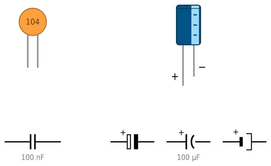
- Ceramic capacitors are small and flat, often orange or yellow. They have small values, from picofarads to microfarads. They have no plus and minus, so they can go either way round.
- Electrolytic capacitors are cylinders, often blue or black. They have large values, from 1 µF to thousands of microfarads. They have a polarity: the longer leg is plus, and a light stripe with minus signs marks minus. They are also marked with the highest voltage they may get, for example 16 V. In a schematic you may come across three symbols, so it is good to know all three. In European schematics plus is a hollow rectangle and minus a filled one. In American ones plus is a straight line and minus a curved one. In the third, plus is a short thick line and minus a thinner line on the other side. There is often a + sign at the plus as well. How to place one on a breadboard is shown on the Breadboard page.
Take care with electrolytic capacitors
- Don't connect one the wrong way round, and don't give it a higher voltage than the one printed on it. It can swell up, leak, or even burst with a bang.
- If a capacitor gets warm or its top bulges, switch off the power at once and call the leader.
- A large capacitor keeps its charge even after you switch off the power (see misconception 22). Don't short its legs to discharge it.
Charging and discharging
A capacitor doesn’t fill up all at once. Let’s look at the circuit in the picture: a 5 V source, a two-way switch, a 10 kΩ resistor and a 100 µF capacitor.
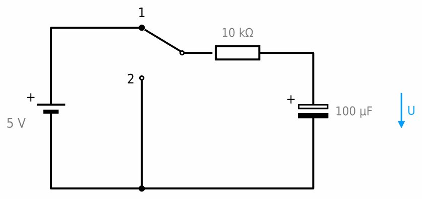
- In position 1 the capacitor charges through the resistor.
- In position 2 the resistor is connected to minus, so the capacitor discharges through it.
The graph shows the voltage across the capacitor (top) and the current through it (bottom). The switch is in position 1 from the start, and after 5 seconds we move it to position 2:
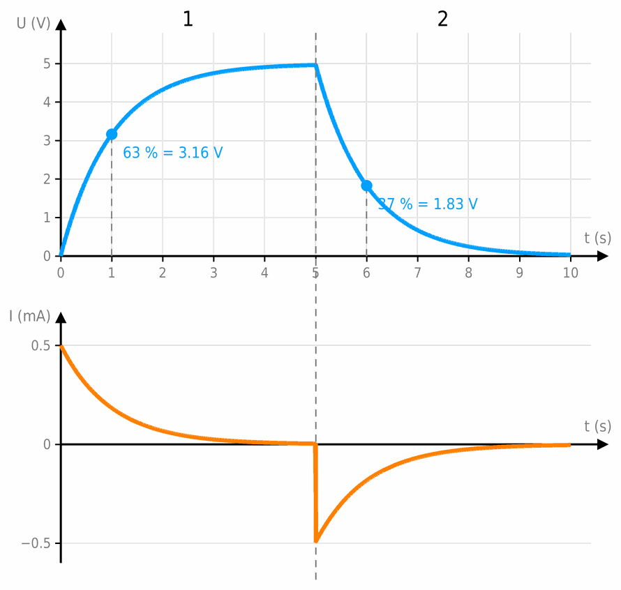
- At the start of charging the capacitor is empty and the current is largest, 5 V / 10 kΩ = 0.5 mA. The voltage rises fast.
- As it charges, less and less voltage is left across the resistor, so the current gets smaller and the voltage rises more and more slowly. A capacitor never charges completely, but after 5 seconds it has 4.97 V, almost the full 5 V.
- While discharging the current flows the other way (it is negative in the graph), and the voltage falls the same way: first fast, then more and more slowly.
That is why a capacitor next to an LED can keep the LED lit for a moment after you disconnect the battery: the LED slowly dims as the capacitor discharges.
Markings on capacitors
On an electrolytic capacitor the value is printed directly, for example 100 µF 16 V. A ceramic one usually has three digits, as on a resistor: the first two are digits, and the third is how many zeros to add, in picofarads.
| Code | Picofarads | Value |
|---|---|---|
| 101 | 10 and one zero = 100 pF | 100 pF |
| 102 | 10 and two zeros = 1000 pF | 1 nF |
| 473 | 47 and three zeros = 47,000 pF | 47 nF |
| 104 | 10 and four zeros = 100,000 pF | 100 nF = 0.1 µF |
You can also convert the code with the capacitor calculator. A letter after the number is the tolerance: J is ±5 %, K ±10 % and M ±20 %.
What are capacitors for?
- Smoothing a voltage. In a rectifier, a capacitor fills the gaps between the waves of the voltage, as on the page Rectifiers and voltage regulators.
- Decoupling. A 100 nF ceramic capacitor next to every chip gives it current for fast changes before that current can arrive from the power supply (misconception 19).
- Measuring time. A capacitor always charges through a resistor at the same speed, so it is used to make timers and circuits that blink.
- Storing energy. A camera’s flash charges a capacitor and then empties it through the lamp in a fraction of a second.
- Touch. A phone’s screen feels your finger because the finger changes the capacitance of tiny plates in the screen.
The capacitor in the Arduino workshop
From here on, this page is for the Arduino workshop.
Charge and the time constant
The charge on a capacitor is:
How fast it charges through a resistor is given by the time constant:
Series and parallel
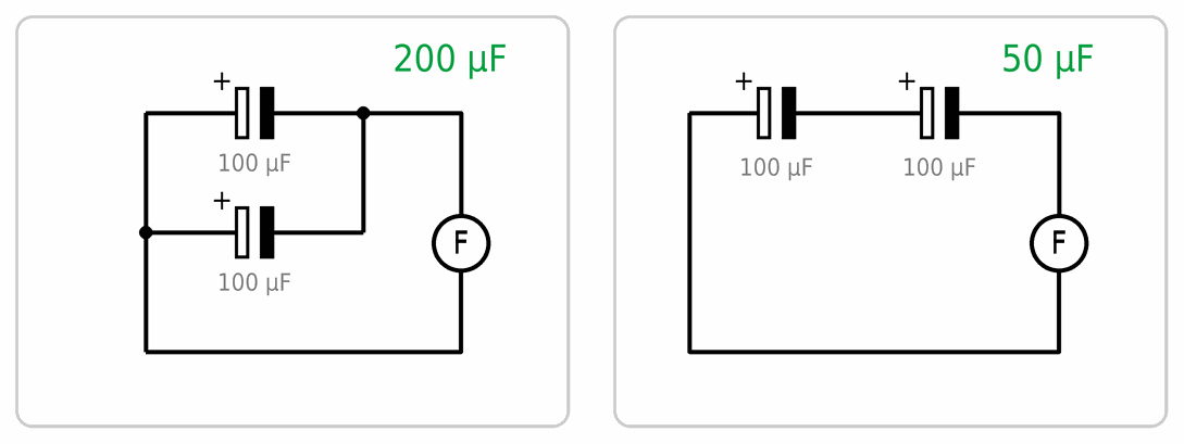
With capacitors it is the other way round from resistors:
- in parallel the capacitances add up: two of 100 µF give 200 µF,
- in series the total capacitance is smaller than each one: two of 100 µF give 50 µF.
A capacitor’s voltage
The voltage printed on a capacitor is the highest it may get. Choose it with a margin: for 5 V a capacitor of at least 10 V, and for 12 V one of at least 25 V. A higher rated voltage does no harm, but the capacitor is then usually bigger.
 What did we learn?
- A capacitor stores charge on two plates separated by an insulator. Capacitance is measured in farads: µF, nF and pF.
- Ceramic capacitors have no polarity. Electrolytic ones do: the longer leg is plus, and the stripe marks minus.
- Through a resistor a capacitor charges and discharges first fast, then more and more slowly. The time constant is τ = R · C: in that time it charges to 63 %.
- The code 104 means 10 and four zeros picofarads, that is 100 nF.
- In parallel capacitances add up, and in series the total is smaller, the other way round from resistors.
Short quiz
1. How do you know which leg of an electrolytic capacitor is minus?
2. What is the capacitance of a ceramic capacitor marked 103?
3. When is the charging current of a capacitor largest?
4. What is the time constant of a 4.7 kΩ resistor and a 100 µF capacitor?
5. You connect two 100 µF capacitors in parallel. What is the total capacitance?
6. A circuit runs on 12 V. May you put in an electrolytic capacitor marked 10 V?