How devices talk: UART, I2C and SPI
How an Arduino, a micro:bit and modules exchange messages: bits through a wire, protocols and clocks, and UART, I2C and SPI, their pins and common mistakes.
A message through a wire
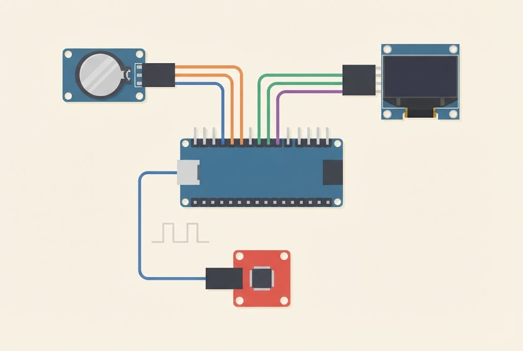
A wire can carry only two states: there is a voltage (1, HIGH) or there isn’t (0, LOW). In the lesson Two traffic lights at a crossroads that is enough, because traffic light A sends traffic light B only two messages: go and stop.
What if we want to send a number, a letter or a whole sentence? Then we send zeros and ones through the wire one after another, just as we can send Morse code with a torch: short, long, short. Every letter and every number can be written with zeros and ones, as a binary number.
An agreement: the protocol
For two devices to understand each other, they must agree in advance:
- what each signal means: which is a zero, which is a one and where a message starts,
- how fast they send: the receiver must know when one bit ends and the next begins,
- who talks when: if both talk at once, nobody understands anybody.
Such an agreement is called a protocol. People have the same problem: in class we put up a hand before we speak, and on a radio we say over when we have finished.
The speed can be agreed in two ways:
- Both devices know the speed in advance. It is as if we agreed that each clap lasts one second. If one device sends faster than the other listens, the receiver reads the wrong bits.
- One device sends a clock. The message goes along one wire and a tick-tock along another, like a conductor waving a baton. On every tick the receiver reads one bit. Then the speed doesn’t matter, as long as everyone keeps to the beat.
Communication you already use
- The USB cable between the computer and the board is also a serial connection: USB stands for Universal Serial Bus. We use it to upload programs, and on an Arduino also to print messages in the serial monitor.
- The micro:bit’s radio sends messages without wires, but by the same rules: in the lesson Radio games all the micro:bits must be in the same group, or they can’t hear each other.
- The Maqueen robot: when the micro:bit tells a motor to drive, it doesn’t switch the motor on directly. It sends a message to a chip on the robot, and the chip drives the motors. That message goes over an I2C connection, described below.
Three connections in the Arduino workshop
From here on, this page is for the Arduino workshop. The modules we connect to an Arduino nearly always use one of three connections:
| UART | I2C | SPI | |
|---|---|---|---|
| Wires (plus GND) | TX, RX | SDA, SCL | MOSI, MISO, SCK, CS |
| Arduino Uno pins | 0 (RX), 1 (TX) | A4 (SDA), A5 (SCL) | 11, 12, 13 and one pin for CS |
| Clock | none, agreed speed | yes | yes |
| How many devices | two | many, each with an address | many, each with its own CS |
| Usual speed | 9600 to 115,200 bits per second | 100,000 or 400,000 bits per second | millions of bits per second |
| Examples | the serial monitor, the DFPlayer MP3 module | two Arduinos, the Maqueen, displays with an I2C module | the RFID card reader, an LED matrix with a MAX7219 |
The same rule applies to all three: the devices must have a common GND. The voltage on a signal wire is measured from ground, so without a common ground the receiver can’t tell whether it is a 0 or a 1 (see misconception 8).
UART
UART (say you-art) is the simplest serial connection. It has two wires, one for each direction:
- TX (transmit) sends,
- RX (receive) receives.
The TX of one device connects to the RX of the other, and the other way round: the wires cross. If you connect TX to TX, both devices talk into the same wire and nobody listens.
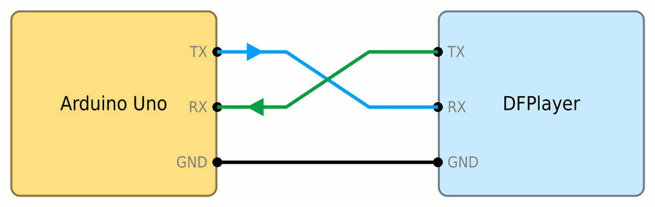
UART has no clock, so both devices must agree on the speed. That is why the program says Serial.begin(9600), and in the serial monitor you choose the same speed, 9600. If the speeds don’t match, strange characters appear in the monitor.
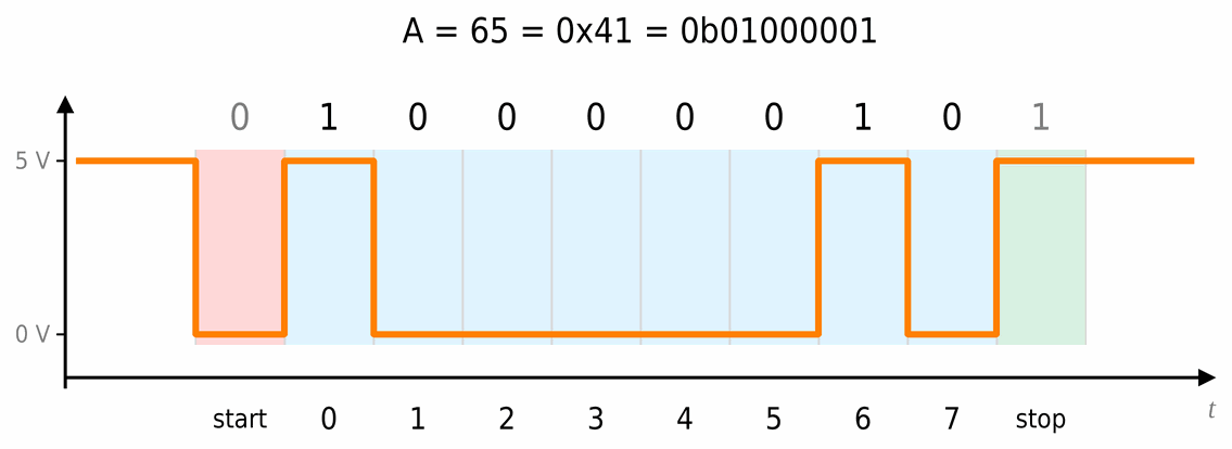
Each message starts with a start bit (the wire drops to 0 for a moment), then come eight data bits, and at the end a stop bit (the wire goes back to 1). This way the receiver knows where each byte begins.
The picture shows the letter A, which is the number 65 in a computer, 0b01000001 in binary. The bits go from the smallest: bit 0, worth 1, is sent first, and bit 7, worth 128, last. That is why on the wire it appears in reverse order: 1, 0, 0, 0, 0, 0, 1, 0.
On most Uno boards, pins 0 and 1 are also connected to USB. While a module is connected to them, uploading a program can fail, and the module receives everything the Arduino sends to the serial monitor. That is why modules with a UART connection are often connected to other pins, using the SoftwareSerial library.
I2C
I2C (say I-squared-C) has only two wires, and many devices can be connected to them:
- SDA (serial data) carries the data, in both directions,
- SCL (serial clock) carries the clock.
One device is the controller. It sends the clock and decides who talks when. The others are targets. In older texts they are called master and slave. Each target has its own address, a number usually written in hexadecimal. The chip that drives the Maqueen robot’s motors has the address 0x10. At the start of a message the controller sends an address, and only the device with that address answers. Two devices with the same address mustn’t be on the same connection.
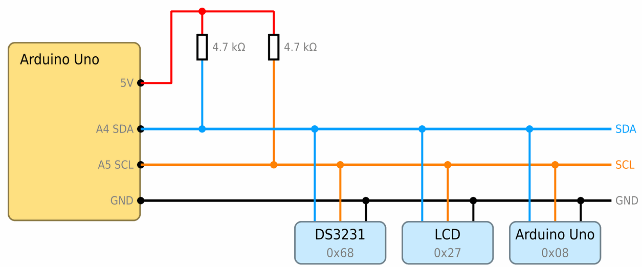
Devices on an I2C connection can only pull a line down to 0. Pull-up resistors, usually 4.7 kΩ, connected from the line to the supply, bring it back to 1. Most modules already have them on board.
On an Arduino Uno, I2C is on pins A4 (SDA) and A5 (SCL). On most boards the same signals are also brought out to two pins next to the AREF pin. In a program we use I2C with the Wire library. This is also how we will connect two Arduinos in the workshop Two Unos over I2C.
I2C was made for short connections inside one device. On wires longer than a few tens of centimetres the signal gets distorted and the connection starts making mistakes.
SPI
SPI is the fastest of the three connections, but it has the most wires:
- MOSI (pin 11) carries data from the controller to the target,
- MISO (pin 12) carries data back,
- SCK (serial clock, pin 13) carries the clock,
- CS or SS (chip select) chooses the device. Each target has its own CS wire, and the controller pulls the wire of the device it wants to talk to down to 0.
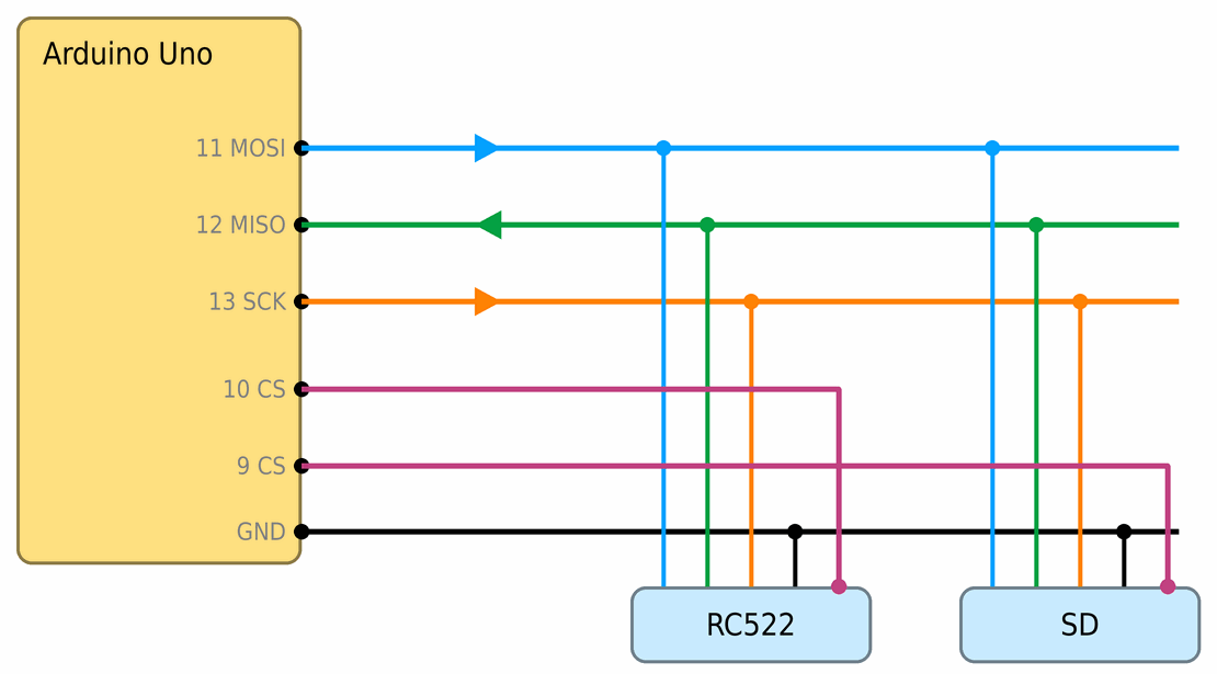
The names come from the words master and slave, so newer texts call them COPI and CIPO (controller and peripheral). On most Uno boards the L LED is connected to pin 13, so it flickers while SPI is working.
Some modules use only part of the SPI connection. The MAX7219 chip, which drives an LED matrix, only receives data, so it has no MISO. Instead it has a DOUT output, which is connected to the input of the next chip. This is how several matrices are connected in a chain, and the Arduino sends the data for all of them over the same three wires.
Mind the module's voltage
An Arduino Uno works at 5 V, and many modules at 3.3 V. The RC522 RFID card reader is powered from the 3V3 pin, never from the 5V pin. Before you connect a module, check which voltage it works at. Why 5 V can damage a 3.3 V device is explained in misconception 9.
When the connection doesn’t work
- There is no common GND. Connect the GND of all the devices.
- UART: TX and RX aren’t crossed. The TX of one device goes to the RX of the other.
- UART: the speeds don’t match. The same speed must be in
Serial.begin(), in the serial monitor and in the module. - UART: the module is on pins 0 and 1. Disconnect it while you upload the program, or connect it to other pins.
- I2C: wrong address. The address is in the module’s instructions. Some modules have jumpers that change the address.
- I2C: there are no pull-up resistors, or the wires are too long.
- SPI: two devices share the same CS, or CS isn’t connected. Each device needs its own CS pin.
- A 3.3 V module is connected to 5 V. The module can be damaged. Ask the leader before you connect it again.
The telegraph, the first serial protocol
Almost 200 years ago people sent messages by telegraph: one wire between two towns and a switch that turned the current on and off. Samuel Morse and Alfred Vail worked out a code in which each letter is a string of short and long signals. The most common letters got the shortest signs: the letter E is just one dot. Telegraph operators had to send at an even rhythm, or the receiver would read the message wrongly. It is the same problem that UART solves with an agreed speed.
 What did we learn?
- Devices exchange messages as strings of zeros and ones. The agreement on how they are sent is called a protocol.
- The receiver must know when each bit starts: either the devices agreed on the speed in advance, or one of them sends a clock.
- UART has two crossed wires and an agreed speed, I2C two wires and addresses, and SPI four wires and a separate CS pin for each device.
- Devices that talk to each other must have a common GND and work at the same voltage.
Short quiz
1. Why must devices agree on how fast they send bits?
2. You see only strange characters in the serial monitor. What do you check first?
Serial.begin() in the program.3. How are the TX and RX wires of two devices connected?
4. Three modules are connected to the same I2C connection. How do they know which one a message is for?
5. Why does an SPI connection have a CS pin?
6. Why mustn't you power the RC522 RFID card reader from the 5V pin?