
Diagrams
What block diagrams, schematics, wiring diagrams, flowcharts and timing diagrams are for, and how to read a schematic, with traffic light and SoundLab examples.
When we build an electronic device, we draw it in more than one way. Each drawing answers a different question:
- block diagram: what the device does and which larger parts it is made of;
- schematic: how the parts are connected electrically, down to the last pin;
- wiring diagram: where each component and each wire goes on the breadboard.
For programs we draw two more kinds of diagram, the flowchart and the timing diagram. On this page you will get to know all of them.
Block diagram
A block diagram shows a device as a few large parts, called blocks. Each block is a rectangle with a name, and arrows show where the signal travels: from the inputs, through processing, to the outputs. We don’t draw resistors, wires or pins.
We draw a block diagram at the start of a project, while we plan it. It helps us answer these questions:
- which inputs do we have (buttons, sensors, potentiometers),
- what processes the signals (usually an Arduino or a micro:bit with its program),
- what are the outputs (LEDs, a speaker, a motor),
- where does the power come from.
We already met the same pattern in the micro:bit lesson Smart systems and connected devices: input ⇒ the program decides ⇒ output.
In our block diagrams a solid black arrow is a signal and a dashed red arrow is power. Sometimes the arrow is also labelled with the pins the block is connected to.
Schematic
A schematic (circuit schematic) shows each component with its symbol and all the electrical connections between the components. Someone else can build the same circuit from a schematic without any further explanation, and we use it to check that our wiring is correct. We met the component symbols on the page Electronic components, symbols and schematics.
How to read a schematic
- A line is a connection, not a wire. A schematic shows what is connected to what, not what the wire looks like or how long it is. On the breadboard the parts can sit in a completely different place than on the schematic.
- A dot means a connection. When two lines cross and there is a dot where they meet, they are connected. If they cross without a dot, one just passes over the other and they are not connected.
- Ground and power symbols replace long lines. All points with a ground symbol (GND) next to them are connected to each other, even though no line is drawn between them. The same goes for VCC, the power supply (5 V for us).
- Every component has a label: letters for its type and a number. R1 is the first resistor, C1 the first capacitor, D1 the first diode (an LED is a diode too), U1 a chip or module (for example the Arduino), SW1 a button, RV1 a potentiometer, LS1 a speaker.
- The value is written next to the label: 220 Ω, 10k (10 kΩ), 100 µF.
Careful: the label D1 on a schematic is the first diode, not pin D1 of the Arduino. You read the Arduino’s pins along the edge of the rectangle that stands for the Arduino on the schematic.
One circuit, three drawings: the traffic light
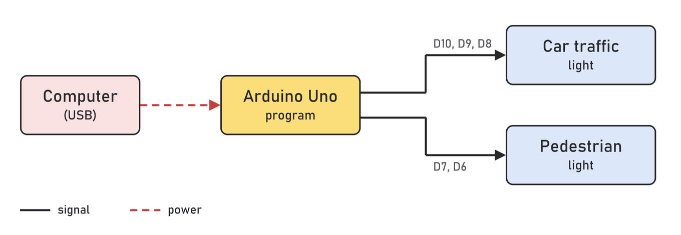
Let’s look at the circuit from the lesson Traffic lights for cars and pedestrians, Exercise 4. An Arduino Uno controls a traffic light for cars and a pedestrian light.
The block diagram has only four blocks. The computer powers the Arduino through the USB cable, and the program in the Arduino switches the lights of both traffic lights:
The schematic shows every part and every connection:
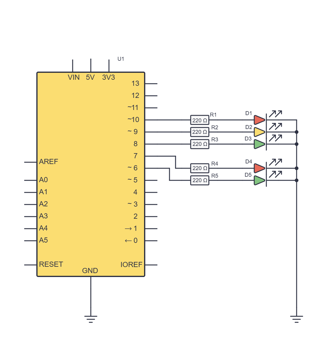
| Block | Parts on the schematic | Arduino pins |
|---|---|---|
| Arduino Uno | U1 | – |
| Car traffic light | R1–R3, D1–D3 | D10, D9, D8 |
| Pedestrian light | R4, R5, D4, D5 | D7, D6 |
| Computer (USB) | not on the schematic | – |
Find the reading rules on this schematic:
- the dots on the vertical line on the right connect the shorter legs (cathodes) of all the LEDs;
- the two GND symbols show that the LEDs and the Arduino’s GND are connected, even though no line is drawn between them;
- D1 to D5 are LEDs, not Arduino pins.
The computer is not on the schematic because it isn’t part of the circuit: it only powers the Arduino through the USB cable.
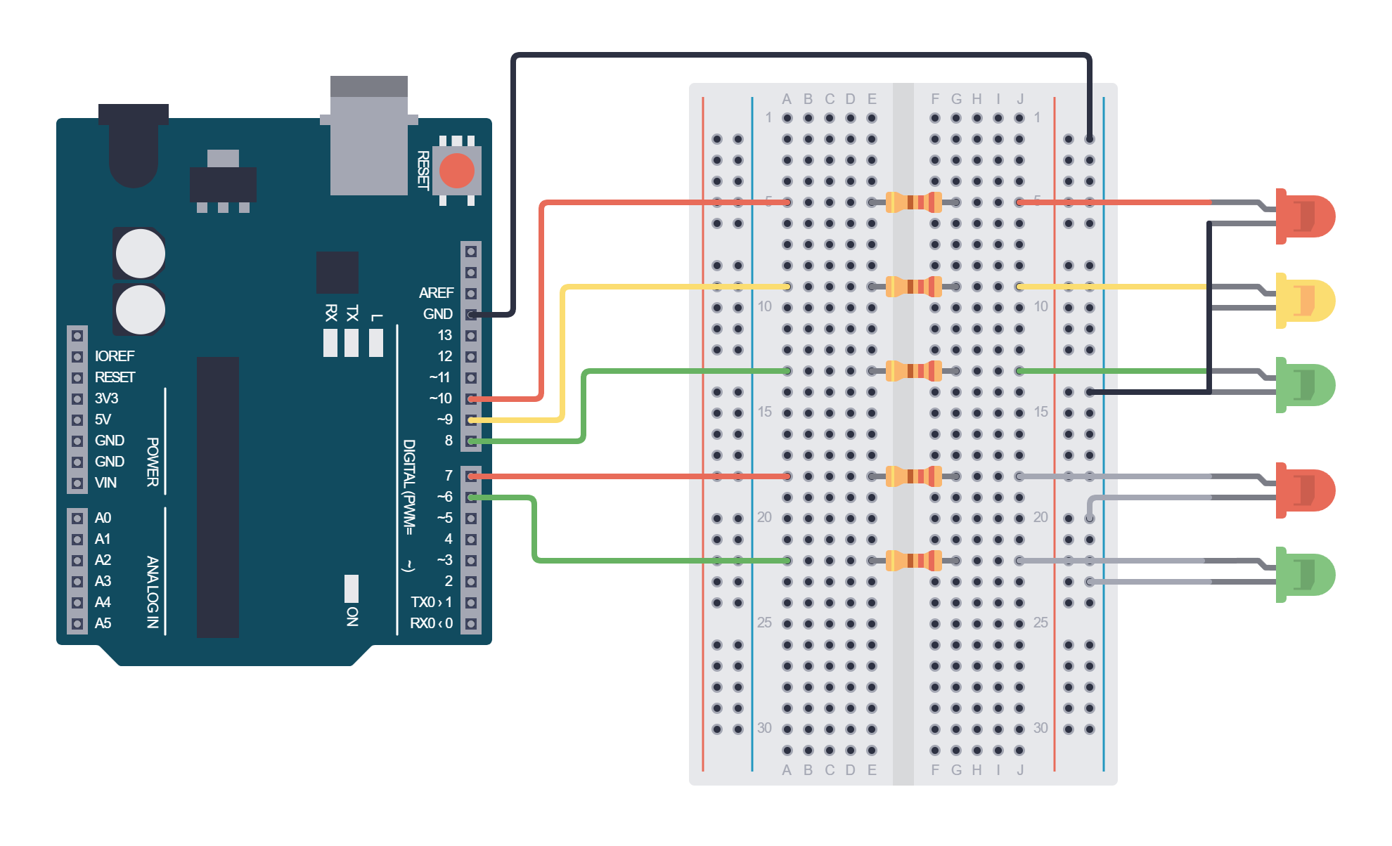
The wiring diagram shows the same circuit the way it looks on the breadboard. You build the circuit from it, and you use the schematic to check that the wiring is correct. How the breadboard holes are connected is explained on the page Breadboard.
A bigger example: SoundLab
The bigger the project, the more useful the block diagram, because the schematic has many parts. The SoundLab project is a small musical instrument. 17 buttons are used to choose notes, and 8 potentiometers change the sound, including the ADSR envelope and FM modulation (the terms are explained on the project page). The Arduino Nano reads the inputs, calculates the sound and sends the audio signal to pin D9. The signal then passes through the volume control to the LM386 amplifier, and the amplifier drives the speaker.
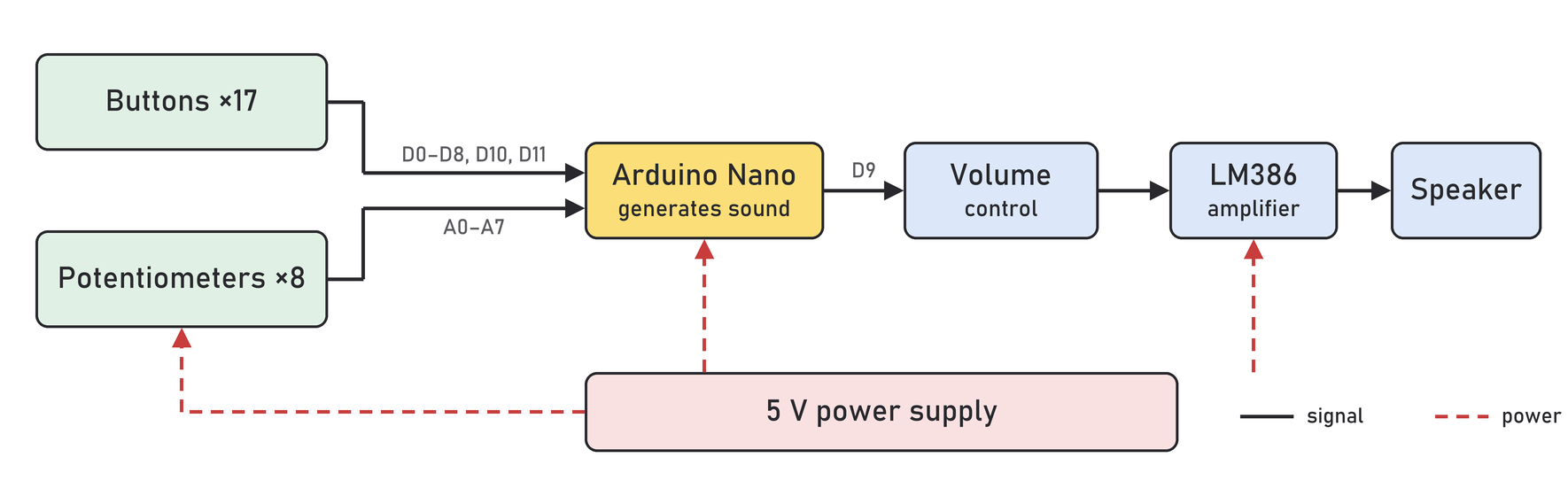
The Arduino Nano is a small version of the Arduino Uno with the same chip. It has two more analogue inputs, A6 and A7, so all 8 potentiometers fit on A0–A7. The Arduino Uno only has A0–A5.
On the SoundLab schematic, the orange boxes mark the parts from the block diagram:
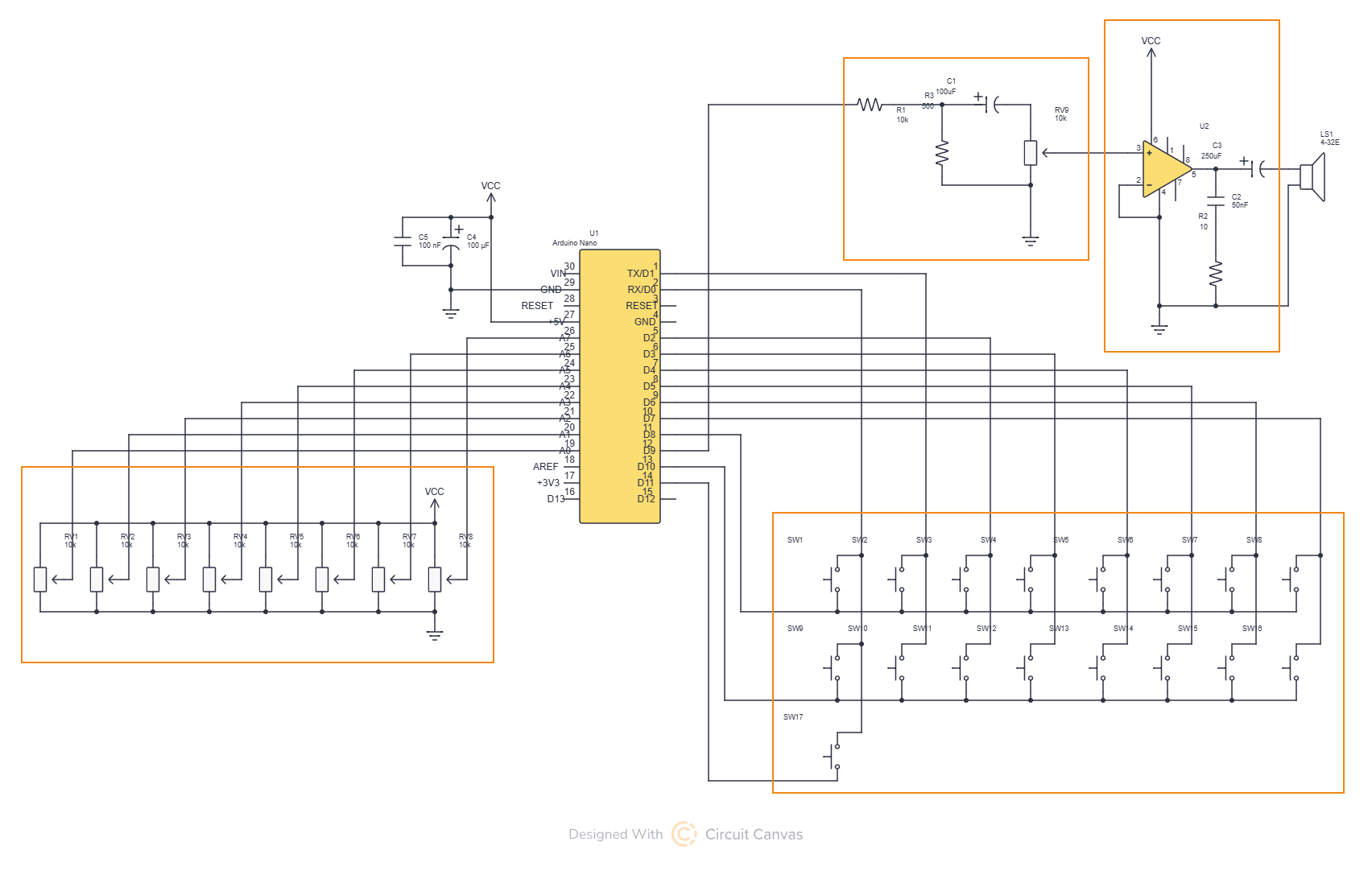
| Block | Parts on the schematic | Where on the schematic |
|---|---|---|
| Buttons | SW1–SW17 | box at the bottom right |
| Potentiometers | RV1–RV8 | box at the bottom left |
| Arduino Nano | U1 | in the middle, no box |
| Volume control | R1, R3, C1, RV9 | box at the top in the middle |
| Amplifier | U2 (LM386), C2, C3, R2 | box at the top right |
| Speaker | LS1 | to the right of the amplifier |
| 5 V power supply | VCC, C4, C5 | to the left of the Arduino |
In the volume control block, resistors R1 and R3 reduce the signal from pin D9 to a level the amplifier can take, capacitor C1 lets the sound through and blocks the DC voltage, and RV9 is the volume potentiometer. Capacitors C4 and C5 smooth the supply voltage. None of these parts are on the block diagram, because it only shows what a block does.
17 buttons on 11 pins
SoundLab's buttons are not each connected to their own pin. They are arranged in a grid (a matrix) of 3 rows and 8 columns. The rows are connected to D8, D10 and D11, and the columns to D0–D7. The program calls the rows one at a time and checks which column the signal shows up on. That way 17 buttons need only 11 pins.
Other kinds of diagram
The first three drawings in the table describe a circuit, and the last two a program.
| Drawing | What it shows | When we use it | Example |
|---|---|---|---|
| Block diagram | the larger parts of a device and the signal flow | when we plan a project and explain the idea | this page |
| Schematic | all components and electrical connections | when we build a circuit and check the wiring | Electronic components, symbols and schematics |
| Wiring diagram | where each component and wire goes on the breadboard | when we build the circuit in the workshop | Breadboard |
| Flowchart | the steps of a program and their order | when we plan a program | My first program in MakeCode |
| Timing diagram | how states change over time | when timing matters in a program | Two traffic lights at a crossroads |
Exercises
- In the lesson Traffic lights for cars and pedestrians, Exercise 5, we add a buzzer to the traffic light. Draw a block diagram of that circuit. Which block do you add, and which pin is it connected to?
- On the SoundLab schematic, find two lines that cross without a dot. Are they connected?
- Choose a circuit from one of the earlier lessons and draw its block diagram. Then mark on its schematic which parts belong to which block.
 What did we learn?
- A block diagram shows what a device does, a schematic how it is connected, and a wiring diagram where each wire goes on the breadboard.
- On a schematic a line means a connection, and a dot where lines cross means they are joined. Lines that cross without a dot are not connected.
- All points with a GND symbol are connected to each other, even though no line is drawn between them.
- Every component on a schematic has a label (R1, C1, D1, U1) and a value.
- We start a project with a block diagram, and we build and check the circuit using the schematic.