
Diode
How a diode lets current through one way only: anode and cathode, the 0.7 V forward voltage, reverse-polarity protection, the relay diode and diode types.
What is a diode?
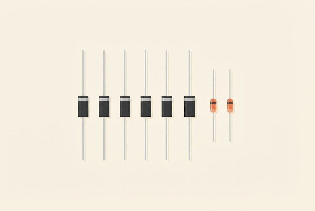
A diode is a component that lets current through in one direction only. It works like the valve on a bicycle tyre: the pump pushes air into the tyre, but the air doesn’t come back out.
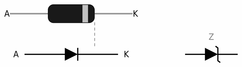
A diode has two legs: the anode (A) and the cathode (K). Current flows from the anode to the cathode. The cathode is marked with a band on the body. In the diode’s symbol the triangle shows the direction of the current, and the bar is the cathode, like the band on the body.
A diode in a circuit
The picture shows two identical circuits with a battery, a diode and a lamp. They differ only in which way round the diode is:
- on the left the anode faces the battery’s plus: the diode conducts, current flows and the lamp lights up,
- on the right the diode is the other way round: the current can’t get through, so the lamp stays dark.
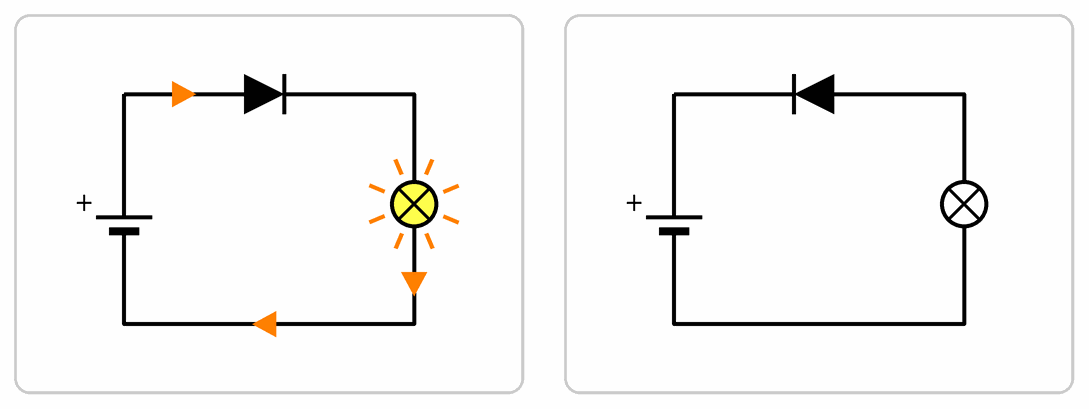
A diode the wrong way round isn’t broken, it just doesn’t let current through. Turn it round and the circuit works.
The forward voltage
A diode doesn’t start conducting as soon as it gets a little voltage. The graph shows the current through a 1N4007 diode as the voltage across it rises:
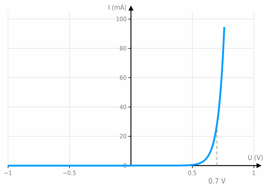
- Below about 0.5 V almost no current flows through the diode.
- Around 0.7 V the current rises steeply. While the diode conducts, about 0.7 V is left across it, whether 10 mA or 100 mA flows. This voltage is called the forward voltage.
- When the diode is the other way round (the negative voltages in the graph), the current is almost zero. A 1N4007 diode withstands up to 1000 V this way. Only above that does it break down and get damaged.
So a diode isn’t a resistor: Ohm's law with one fixed resistance doesn’t apply to it, just as it doesn’t to an LED, which is also a diode.
What are diodes for?
- Reverse-polarity protection. A diode in series with the supply’s plus lets current through when the battery is the right way round. When someone puts it in the other way round, the diode doesn’t conduct, as on the right of the picture above, and the circuit is unharmed. The price is 0.7 V less voltage for the circuit.
- Rectifying. Diodes turn an AC voltage into a DC one: this is explained on the page Rectifiers and voltage regulators.
- Protection from a coil. A diode next to a relay, a solenoid or a motor protects the transistor that switches it, as in the section below.
- Switch matrices. Diodes prevent false key presses when several keys are pressed at once, as in the lesson Many switches on few pins.
- Light. An LED is a diode that shines while current flows through it.
The diode in the Arduino workshop
From here on, this page is for the Arduino workshop.
The protection diode next to a coil
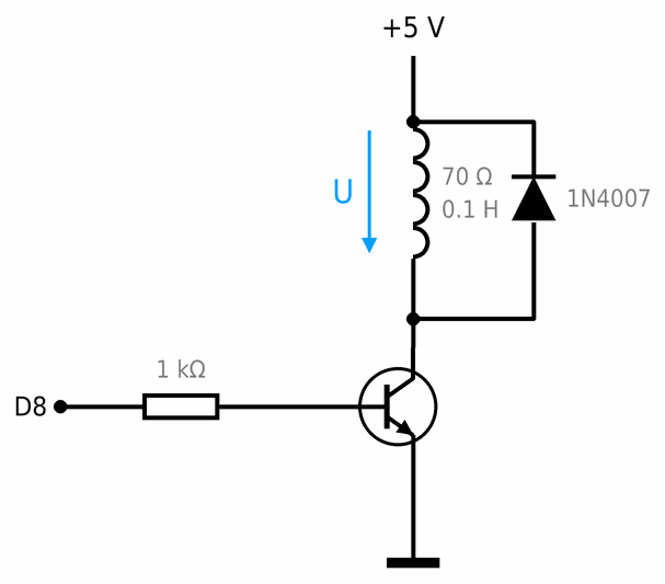
A diode connected across the coil, cathode towards the plus, doesn’t conduct while the transistor is on, because it faces against the voltage across the coil. When the coil reverses its voltage, the diode faces exactly the way of that voltage: it conducts, and the coil’s current flows round through the diode and slowly dies away. The voltage across the coil is then only −0.7 V, the voltage across the diode, and the collector is at 5 V + 0.7 V = 5.7 V.
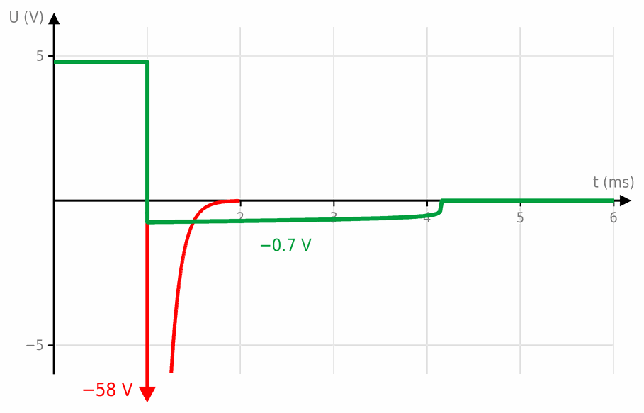
The graph was calculated for a 70 Ω, 0.1 H relay coil on 5 V. 71 mA flows through it. When the transistor switches off at 1 ms, that current keeps flowing through the diode for about 3 ms more, getting smaller all the time, while the voltage across the coil stays at about −0.7 V. Without the diode the voltage across the coil drops at once to about −58 V, so the collector is at about 62 V, and a small transistor such as the BC547 only withstands 45 V. How far the voltage drops depends on the coil and on what breaks down first; with larger coils it reaches hundreds of volts. That is why we put a diode next to every relay, solenoid and motor (misconception 25).
Kinds of diode
| Kind | Example | Forward voltage | What it is for |
|---|---|---|---|
| silicon rectifier | 1N4007 | about 0.7 V | rectifying, protection, currents up to 1 A |
| silicon signal | 1N4148 | about 0.7 V | small currents, key matrices |
| Schottky | 1N5819 | 0.2 to 0.5 V | when you need a smaller voltage loss |
| Zener | BZX55C5V1 | holds a fixed voltage in reverse, here 5.1 V | a simple voltage reference |
| light-emitting (LED) | red 5 mm | 1.8 to 3 V | light, see LED |
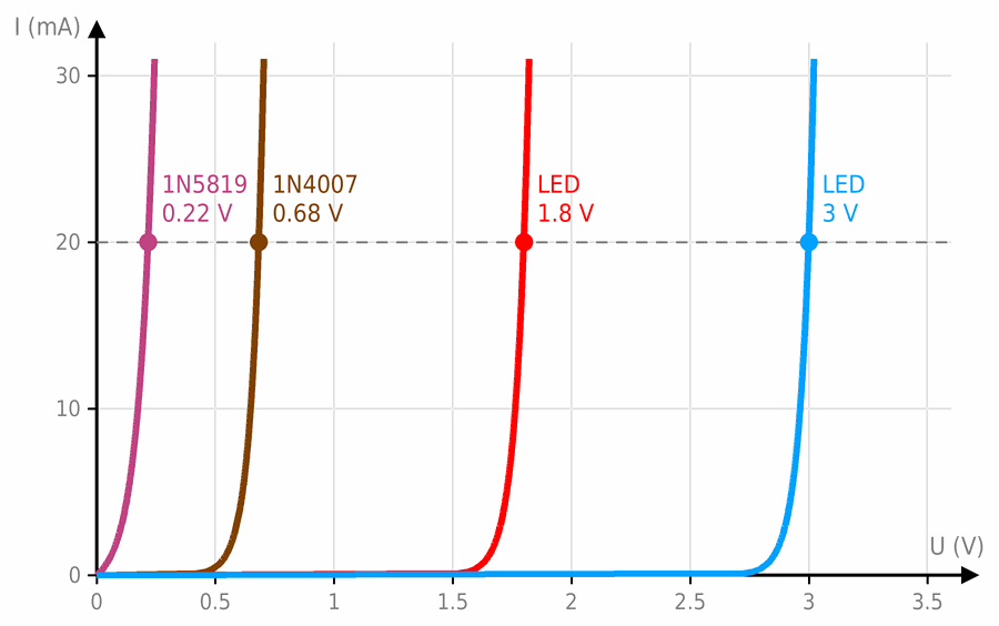
The forward voltage depends on the material the diode is made of. The graph shows the current through four diodes from the table. At 20 mA, 0.22 V is left across the Schottky diode, 0.68 V across the silicon one, 1.8 V across the red LED and 3 V across the blue one. All four curves have the same shape: while the voltage is small they don’t conduct, and then the current rises steeply.
The Zener diode
An ordinary diode the wrong way round doesn’t conduct. When the reverse voltage gets too high, it breaks down: it suddenly starts to conduct and is damaged. A Zener diode is made precisely to break down, at an exact voltage, its Zener voltage, without being damaged, as long as a resistor limits its current. In a schematic you recognise it by the bar bent at its ends, as in the picture at the top of the page.
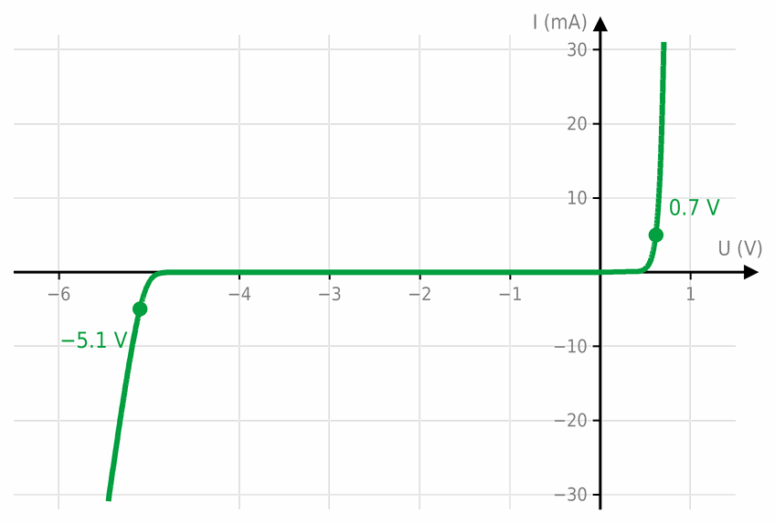
The graph shows a BZX55C5V1 Zener diode both ways round. Forwards (on the right) it behaves like an ordinary diode and conducts from about 0.7 V. In reverse (on the left) it doesn’t conduct until the voltage reaches about 5 V, and then the current rises steeply while the voltage stays almost the same: at 5 mA it is 5.1 V, and at 30 mA only 5.4 V. That is why we connect a Zener diode the other way round, cathode towards the plus. The code 5V1 means 5.1 V and is read like 4k7 on a resistor, and the letter C before it means a tolerance of ±5 %.
Typical use: a simple voltage regulator. A Zener diode and a resistor give a steady voltage from a voltage that changes:
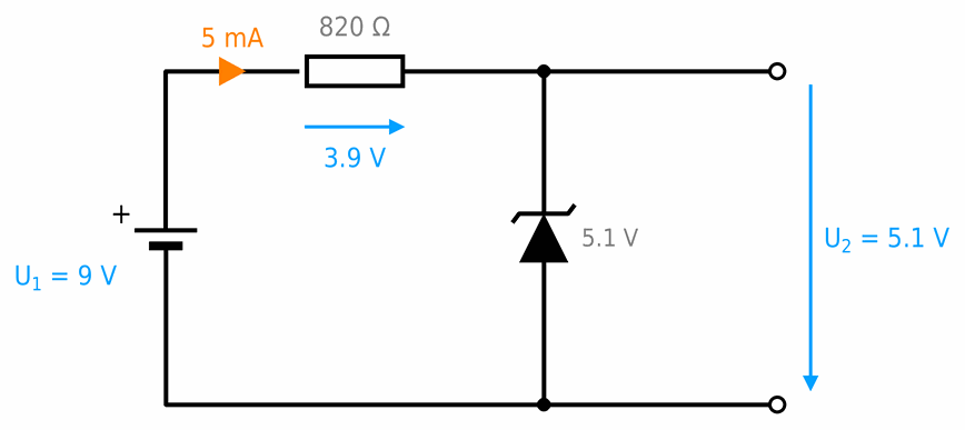
The graph shows what happens at the output when the input voltage U1 changes from 0 to 12 V:
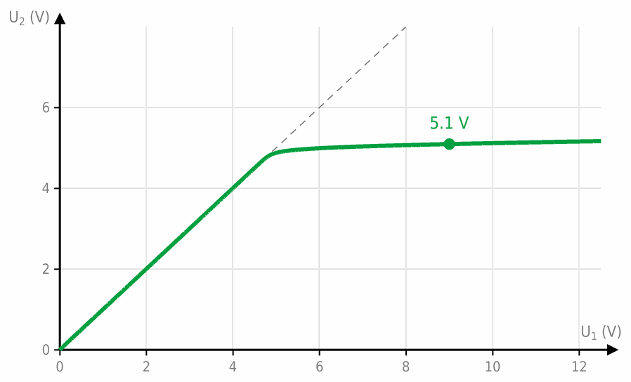
Such a regulator can only supply a small current. A load at the output takes current that would otherwise flow through the Zener diode, and here that is only a few milliamps. So it is used as a voltage reference or to protect an input: a 5.1 V Zener diode between an Arduino input and GND, with a resistor towards the signal, doesn’t let the voltage on the pin rise above about 5 V. To power circuits we use a voltage regulator, described on the page Rectifiers and voltage regulators.
The Schottky diode
A Schottky diode is made from a junction of a metal and a semiconductor, not from two layers of semiconductor like an ordinary one. That is why less voltage is left across it: according to the graph above, 0.22 V at 20 mA, about 0.3 V at 100 mA and about 0.47 V at 1 A, roughly half as much as across a silicon diode. It also switches on and off faster, so it is used in chargers and switching regulators. It has two drawbacks: it withstands a smaller reverse voltage (the 1N5819 only 40 V, the 1N4007 1000 V), and in reverse it lets through a little more current. In a schematic it is drawn as an ordinary diode whose bar is bent into an S.
Typical use: reverse-polarity protection when every volt counts. The picture shows the same circuit with two diodes: a 4.5 V battery (three AA batteries), a protection diode and a 39 Ω load, which needs about 100 mA:
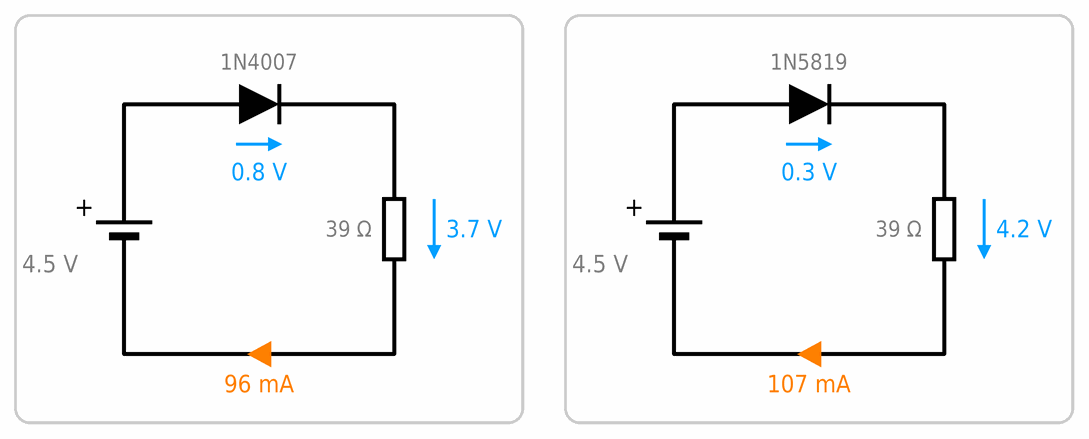
- with a 1N4007 silicon diode, 0.8 V is left across it, so the load only gets 3.7 V,
- with a 1N5819 Schottky diode, 0.3 V is left across it, so the load gets 4.2 V.
The Schottky diode also turns half as much power into heat: 0.32 V · 107 mA ≈ 34 mW, against 0.76 V · 96 mA ≈ 73 mW for the silicon one. For the same reason, small solar chargers have a Schottky diode between the panel and the battery: by day it lets current into the battery, and at night it doesn’t let the battery run down through the panel.
The light-emitting diode (LED)
An LED is a diode like the others: it lets current through only from the anode to the cathode, and it doesn’t conduct until the voltage reaches its forward voltage. It differs in three ways:
- while it conducts, it shines, and the colour of the light depends on the material,
- its forward voltage is much higher, from 1.8 V for red to 3 V for blue and white, as in the graph above,
- in reverse it only withstands about 5 V. That is why we never use it instead of a rectifier or protection diode.
As with every diode, the current through an LED rises steeply above the forward voltage, so we always connect it through a resistor. How to work it out is explained on the LED page.
Typical use: a polarity tester. Two LEDs connected opposite ways round show which wire is plus:
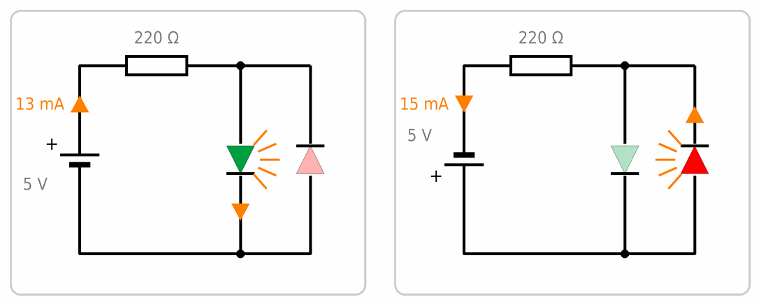
- When plus is on the top wire (left), the current flows through the green LED, 13 mA, and it lights up.
- When plus is on the bottom wire (right), the current flows through the red one, 15 mA.
The LEDs also protect each other: the one that doesn’t conduct only gets the other one’s forward voltage in reverse, about 2 V, far less than the 5 V it may. With such a tester you can check which wire of an adapter or battery holder up to 5 V is plus. For higher voltages you need a larger resistor, for example 470 Ω for 9 V.
Limits and heat
A 1N4007 diode may carry at most 1 A. It too turns power into heat: P = 0.7 V · I. At 1 A that is 0.7 W, and the diode gets warm.
You can easily check a diode and its direction with a multimeter: one way it shows about 0.6 V, and the other way OL.
 What did we learn?
- A diode lets current through only from the anode to the cathode. The cathode is marked with a band on the body and a bar in the symbol.
- A silicon diode only starts conducting at about 0.7 V, and while it conducts, that voltage is left across it.
- Diodes protect against reverse polarity, rectify AC voltage and prevent false presses in a key matrix.
- A Zener diode, connected the other way round and through a resistor, holds a steady voltage, for example 5.1 V.
- Less voltage is left across a Schottky diode than across a silicon one, about 0.3 V, but it withstands a smaller reverse voltage.
- An LED is a diode that shines. Its forward voltage is 1.8 to 3 V, and in reverse it only withstands about 5 V.
- Next to the coil of a relay, solenoid or motor we always put a protection diode, cathode towards the plus. Without it, the coil’s voltage reverses when it is switched off, and the transistor gets tens or hundreds of volts.
Short quiz
1. On which side of a diode is the cathode?
2. In a circuit with a battery, a diode and a lamp, the lamp doesn't light up. What do you check first?
3. A battery has 9 V, and the circuit is protected by a reverse-polarity diode. What voltage does the circuit get?
4. Why do we put a diode next to a relay, and which way round does it go?
5. You need a diode that takes away as little voltage as possible. Which do you choose?
6. A 5.1 V Zener diode needs about 5 mA from a 12 V source. Which resistor do you take?
7. Why mustn't you use an LED as a reverse-polarity protection diode?