ESP32 and ESP8266: microcontrollers with Wi-Fi
ESP32-S3, ESP32-C3, ESP8266 and the other Espressif chips: Wi-Fi, Bluetooth, memory, pins, power supply and which one to choose for which project.
An Arduino Uno can switch on LEDs and read sensors, but it can’t get onto the internet on its own. The Chinese company Espressif makes microcontrollers that have Wi-Fi in the same chip, and many have Bluetooth too. The first well-known one was the ESP8266 from 2014, and the ESP32 followed in 2016. Today it is a whole family of chips whose names start with ESP32.
They are programmed in the same Arduino IDE and the same language as an Arduino, but they have much more memory and a faster processor: the ESP32-S3 has 256 times more working memory than the Uno and a clock 15 times faster. That is why they are common in smart homes, sensors that send data, smart bulbs and smart plugs. This page is mostly about three members of the family: the ESP32-S3, the ESP32-C3 and the ESP8266. Where each of their pins is, is on this page; for the Arduino, see the Pinouts and Arduino boards: Uno, Nano, Mega and Giga pages.
The pins work at 3.3 V
All ESP chips work at 3.3 V. A pin may take at most 3.6 V, so an output of an Arduino Uno or of a 5 V module can damage it. A connection like that needs a level shifter or a voltage divider. One pin of an ESP32 gives at most 40 mA, and one of an ESP8266 only 12 mA, so connect an LED through a resistor of at least 150 Ω.
Chip, module and DevKit
The ESP32-S3 chip itself is 7 × 7 mm. To work, it needs flash memory for the program, a crystal for the clock and an antenna. That is why it is rarely soldered on its own, but comes in a module: a small printed circuit board with the chip, the flash memory, the crystal and the antenna. The chip and the memory are hidden under a metal cover, and the antenna is a copper track at the end of the module. The module has already been tested and approved for working with radio waves, which makes it easier for device makers to build it in.
A module can’t be plugged straight into a breadboard or connected to a computer. That is what a DevKit (development kit) is for: the module on a bigger printed circuit board with a USB socket, a voltage regulator, buttons and pin headers. The module’s name says what is in it: the ESP32-S3-WROOM-1-N8R8 has an ESP32-S3 chip, 8 MB of flash memory (N8) and 8 MB of extra RAM, PSRAM (R8). 1U instead of 1 means that instead of an antenna on the board the module has a socket for an external antenna.
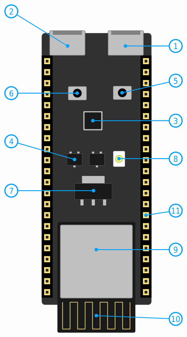
The picture shows Espressif’s ESP32-S3-DevKitC-1 (version 1.1):
- The UART USB socket: the computer uploads programs through it and receives messages for the Serial Monitor. The DevKit also gets its 5 V supply through it.
- The USB USB socket: connected straight to the ESP32-S3, to pins 19 and 20. Through it the ESP32-S3 can pretend to be a keyboard, a mouse or a USB stick to the computer.
- The USB-to-UART chip turns USB into a serial UART connection, like the USB chip on an Arduino Uno.
- Two transistors: when it uploads a program, the computer uses them to press the BOOT and RESET buttons by itself.
- BOOT: if you hold it while you press RESET, the ESP32-S3 waits for a new program. That helps when uploading doesn’t start by itself.
- RESET restarts the program.
- The voltage regulator makes 3.3 V for the module from the 5 V of the USB.
- The RGB LED on pin 38, which can shine in any colour. On the first version of the DevKit it was on pin 48.
- The ESP32-S3-WROOM-1 module: under the tin cover are the chip, the flash, the PSRAM and the crystal.
- The antenna: it sticks out over the edge of the DevKit. Don’t put anything metal on it or under it, or your hand, because that weakens the signal.
- The pin headers: two of 22 pins each.
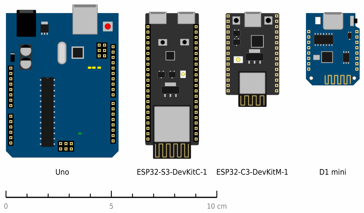
The DevKit is 62.7 mm long and 25.4 mm wide. When you plug it in across the middle gap of a breadboard, only one free hole is left on each side. So rather put it across two breadboards, as on the Breadboard page.
The ESP family
All ESP32 chips are programmed the same way, but they differ in their processor and in the radio connections they have. Wi-Fi 4 is the older standard (802.11n), and Wi-Fi 6 the newer one (802.11ax), which works better when there are many devices on the same network. Almost all of them work on 2.4 GHz only. Thread and Zigbee are smart home networks (the 802.15.4 standard) that bulbs, switches and sensors use to talk without Wi-Fi.
| Chip | Processor | Clock | RAM | Wi-Fi | Bluetooth | Thread, Zigbee | USB |
|---|---|---|---|---|---|---|---|
| ESP8266 | 1 core, Tensilica L106 | 80 or 160 MHz | about 50 KB for the program | Wi-Fi 4 | no | no | no |
| ESP32 | 2 cores, Xtensa LX6 | 240 MHz | 520 KB | Wi-Fi 4 | 4.2: Classic and BLE | no | no |
| ESP32-S2 | 1 core, Xtensa LX7 | 240 MHz | 320 KB | Wi-Fi 4 | no | no | yes |
| ESP32-S3 | 2 cores, Xtensa LX7 | 240 MHz | 512 KB | Wi-Fi 4 | 5 (BLE) | no | yes |
| ESP32-C2 | 1 core, RISC-V | 120 MHz | 272 KB | Wi-Fi 4 | 5 (BLE) | no | no |
| ESP32-C3 | 1 core, RISC-V | 160 MHz | 400 KB | Wi-Fi 4 | 5 (BLE) | no | yes |
| ESP32-C5 | 1 core, RISC-V | 240 MHz | 384 KB | Wi-Fi 6, 2.4 and 5 GHz | 5 (BLE) | yes | yes |
| ESP32-C6 | 1 core, RISC-V | 160 MHz | 512 KB | Wi-Fi 6 | 5 (BLE) | yes | yes |
| ESP32-C61 | 1 core, RISC-V | 160 MHz | 320 KB | Wi-Fi 6 | 5 (BLE) | no | yes |
| ESP32-H2 | 1 core, RISC-V | 96 MHz | 320 KB | no | 5 (BLE) | yes | yes |
| ESP32-P4 | 2 cores, RISC-V | 400 MHz | 768 KB and 16 or 32 MB of PSRAM | no | no | no | yes, and fast USB 2.0 |
| Chip | Pins (GPIO) | Analog inputs | Current in deep sleep | Arduino IDE |
|---|---|---|---|---|
| ESP8266 | 17 | 1, from 0 to 1 V | 20 µA | yes, its own package |
| ESP32 | 34 | 18 | 10 µA | yes |
| ESP32-S2 | 43 | 20 | 25 µA | yes |
| ESP32-S3 | 45 | 20 | 7 µA | yes |
| ESP32-C2 | 14 | 5 | 5 µA | no |
| ESP32-C3 | up to 22 | 6 | 5 µA | yes |
| ESP32-C5 | 29 | 6 | 12 µA | yes |
| ESP32-C6 | 30 or 22 | 7 | 7 µA | yes |
| ESP32-C61 | 30 | 4 | 10 µA | no |
| ESP32-H2 | 19 | 5 | 7 µA | yes |
| ESP32-P4 | 55 | 14 | 12 µA | yes |
The numbers are for the chip itself, from Espressif’s datasheets. A DevKit has fewer pins, because the flash memory uses some of them, and draws more current in deep sleep, because the regulator, the USB-to-UART chip and the LEDs draw current too. The deep sleep current is for a sleep in which only the clock and a small RTC memory are on. The Arduino IDE column says whether Espressif’s package for the Arduino IDE supports the chip.
An open processor
The C, H and P series have a RISC-V processor. RISC-V is an instruction set that was created at the University of California, Berkeley in 2010, and anyone may use it without paying for a licence. The older ESP8266, ESP32 and S series have Xtensa processors from Tensilica (now Cadence), which need a paid licence.
ESP32-S3
The ESP32-S3 is the most powerful chip of the family with Wi-Fi and Bluetooth. It has two 240 MHz cores and 512 KB of RAM, and in a module it often comes with 2 to 8 MB of PSRAM. It also has special instructions that speed up calculations with many numbers at once, the kind needed for recognising voice and pictures (artificial intelligence). It has connections for a camera and a display, USB, 14 pins that sense touch and two analog-to-digital converters (ADC) with 20 inputs.
It is used for cameras that send pictures over Wi-Fi, devices with a display, smart speakers that recognise commands, USB keyboards and game controllers, and for every project that doesn’t have enough memory on an Uno.
Check the datasheet before you connect anything
The pictures on this page show the pinout of one version of a DevKit or D1 mini. Other versions, and boards with the same chip from other makers, often have the pins in a different order, and the LED and buttons on other pins. So before you connect anything, look at the datasheet or pinout of exactly your board, by the name and version that are usually printed on it.
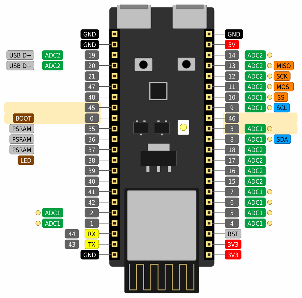
The labels in the picture have the same colours as on the Pinouts page. The number on the DevKit is the pin’s number (GPIO), and that is the number you write in the program: digitalWrite(4, HIGH). SDA, SCL, MOSI, MISO, SCK and SS are the pins the Arduino IDE package uses when you don’t choose others. An ESP32 can move them to almost any pin.
| Label | What it means |
|---|---|
| 3V3 | power: 3V3 and 5V |
| GND | minus, ground |
| 4 | the pin with that number (GPIO) |
| ADC1 | analog input of the first converter (ADC1) or the second (ADC2) |
| a pin that senses touch | |
| TX | UART connection (RX and TX) |
| SDA | I2C connection (SDA and SCL) |
| MOSI | SPI connection (MOSI, MISO, SCK and SS) |
| LED | a pin the DevKit itself uses: an LED, the BOOT button |
| RST | special pins: RST, USB and PSRAM |
What to watch out for:
- The pins in the yellow band (0, 3, 45 and 46) decide how the chip starts. The ESP32-S3 checks their level at the moment it starts. If pin 0 is at GND then, it waits for a new program instead of starting yours. Don’t connect anything to them that pulls them to the other level at start-up, such as a button to GND or a module with a resistor.
- Pins 35, 36 and 37 are not free on modules with eight data lines for the PSRAM, such as N8R8 and N16R8. The chip uses them to talk to the memory.
- Pins 19 and 20 are the USB connection. While you use USB through them, don’t use them for anything else.
- ADC2 shares with Wi-Fi. While Wi-Fi is on, reading an analog input on pins 11 to 20 can fail. To measure while using Wi-Fi, use pins 1 to 10 (ADC1).
- The analog input measures up to about 2.9 V and is not equally accurate over the whole range. For accurate measurements an external converter is better.
- The PSRAM has to be switched on in the Arduino IDE: Tools → PSRAM → OPI PSRAM for modules marked R8 or R16, QSPI PSRAM for R2.
- The RGB LED is not an ordinary LED: it has a small chip of its own. It is switched on with
rgbLedWrite(38, 0, 0, 64): the pin, then red, green and blue from 0 to 255.
ESP32-C3
The ESP32-C3 is a small, cheap chip with one 160 MHz RISC-V core, 400 KB of RAM, Wi-Fi 4 and Bluetooth 5 (BLE). In deep sleep it draws only 5 µA. Many versions have 4 MB of flash memory in the same package, so modules and DevKits with it are very small. It also has USB, but only for uploading programs and the Serial Monitor, not for pretending to be a keyboard.
It is used for smart plugs and bulbs, temperature and humidity sensors that send their data over Wi-Fi, Bluetooth tags and remote controls. It is a good replacement for the ESP8266 in new projects: it has more memory, Bluetooth, a better analog input and USB.
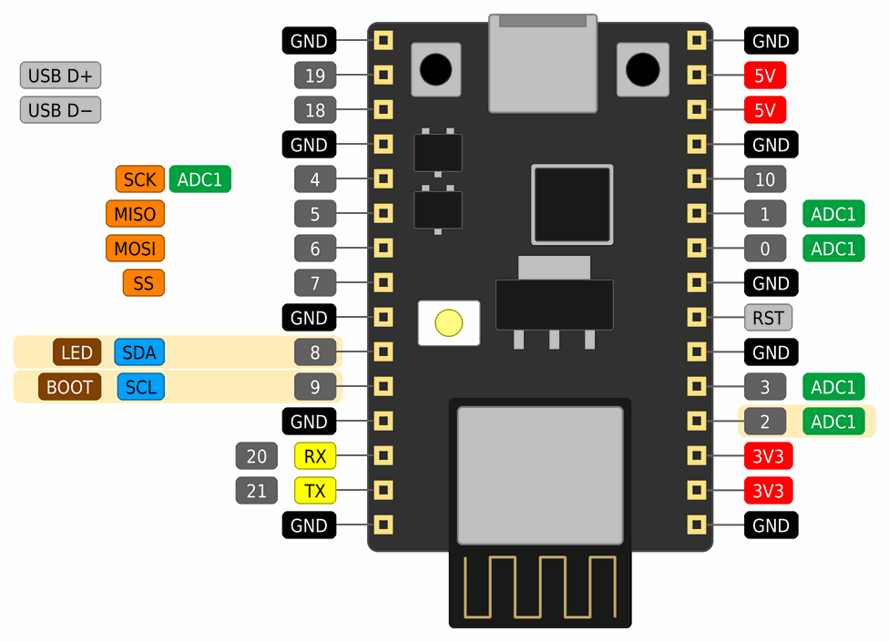
The picture shows Espressif’s ESP32-C3-DevKitM-1, which is 38.9 mm long. What to watch out for:
- The pins in the yellow band (2, 8 and 9) decide how the chip starts. The BOOT button is connected to pin 9 and the RGB LED to pin 8, which is also SDA. If you connect a module to them, check that it doesn’t pull them to the other level at start-up.
- The analog inputs are only on pins 0 to 4. Because of a fault in the chip, the second converter (ADC2, pin 5) doesn’t work reliably, so Espressif’s software no longer supports it.
- Pins 18 and 19 are the USB connection.
- Small DevKits without a USB-to-UART chip only have the chip’s own USB socket. On them the Serial Monitor only works once you switch on Tools → USB CDC On Boot → Enabled in the Arduino IDE.
ESP8266
The ESP8266 is the oldest member of the family. It has one core running at 80 or 160 MHz and Wi-Fi 4, but no Bluetooth. With Wi-Fi on, about 50 KB of RAM is left for the program, which is still twenty-five times more than on an Uno. The program is in an external flash memory, and there is only one analog input, which on the chip itself measures from 0 to 1 V.
Because it is cheap and there are many guides on the internet, it is still in many projects: Wi-Fi plugs, weather stations, LED strips controlled from a mobile phone. It is most often used on the D1 mini and NodeMCU DevKits, and as the small ESP-01 module with eight pins, which needs an external 3.3 V regulator and a USB-to-UART adapter.
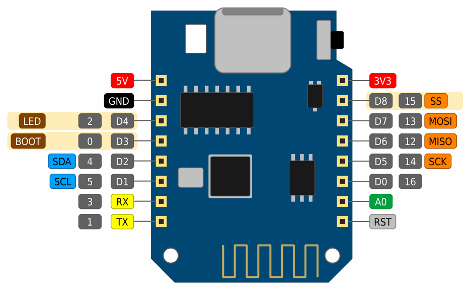
The picture shows a LOLIN D1 mini (version 4), which is 34.3 mm long. The pin’s name (D0 to D8) is printed on it, and in the picture the pin’s number (GPIO) is next to its label. In the program you can write either: D4 and 2 are the same pin. What to watch out for:
- Pins D3, D4 and D8 (GPIO 0, 2 and 15) decide how the chip starts. D3 and D4 must be at 3.3 V at start-up and D8 at GND, and the DevKit has resistors that keep them there. So a button to GND on D3 or D4 must not be pressed while the chip starts.
- The LED on D4 lights up when the pin is
LOW, notHIGH, because it is connected to 3.3 V. - A0 on the D1 mini has a voltage divider, so it measures from 0 to 3.2 V, as a value from 0 to 1023.
- One pin may give at most 12 mA.
- Waking up from deep sleep on the ESP8266 works by pin D0 (GPIO 16) briefly pulling RST low at the end of the sleep. So D0 and RST must be connected with a wire; on the D1 mini v4 there is a solder jumper, JP1, for this.
The other members of the family
- The ESP32 (without a letter) is the first ESP32 and is still on many DevKits, most often with 30 or 38 pins. It is the only one in the family with Classic Bluetooth, which it uses to send sound to a speaker or headphones and to talk to a mobile phone as a serial port. It also has two analog outputs (DAC) and a connection for Ethernet. Pins 34 to 39 are inputs only, pins 0, 2, 5, 12 and 15 decide how it starts, and ADC2 doesn’t work while Wi-Fi is on.
- The ESP32-S2 has one core, Wi-Fi and USB, but no Bluetooth. It is good for USB devices with Wi-Fi.
- The ESP32-C2 is the smallest and cheapest chip with Wi-Fi and Bluetooth, for simple products made in large numbers. Espressif’s package for the Arduino IDE doesn’t support it.
- The ESP32-C5 is the only one that also works on 5 GHz, where it is less crowded than on 2.4 GHz. It has Wi-Fi 6, Bluetooth and Thread.
- The ESP32-C6 has Wi-Fi 6, Bluetooth, Thread and Zigbee, so it is common in smart home devices. Besides the main core it has a small 20 MHz core that works while the main one sleeps.
- The ESP32-C61 has Wi-Fi 6 and Bluetooth, but no Thread or Zigbee, and PSRAM can be added to it.
- The ESP32-H2 has no Wi-Fi, only Bluetooth, Thread and Zigbee. It is for battery-powered sensors and switches that talk to a smart home hub.
- The ESP32-P4 has no radio connections, but it is the fastest in the family: two 400 MHz cores, fast USB, Ethernet and connections for a large display and a camera. When it needs Wi-Fi, a second chip is put next to it, for example an ESP32-C6.
Which one to choose?
- A first project with Wi-Fi, a sensor that sends data to the network, a Wi-Fi plug: ESP32-C3. It is small, cheap and draws little current. If you want more pins and memory, ESP32-S3.
- A camera, a display, sound, recognising voice or pictures: ESP32-S3 with PSRAM.
- A USB keyboard, mouse or game controller: ESP32-S3, or without Bluetooth ESP32-S2.
- Sound over Bluetooth to a speaker or headphones: ESP32, because only it has Classic Bluetooth.
- A battery-powered device that wakes up rarely: ESP32-C3, C6 or H2, on a DevKit that draws little current while it sleeps (see Power supply).
- A smart home with Thread, Zigbee or Matter: ESP32-C6, or without Wi-Fi ESP32-H2.
- Wi-Fi on 5 GHz: ESP32-C5.
- A large display, a camera and high speed, without radio: ESP32-P4.
- A project with ready-made instructions for the ESP8266: the ESP8266 still works, but for a new project choose the ESP32-C3 instead.
The Arduino Uno is still better when you need 5 V, tougher pins and an easy start. If 5 V reaches an ESP pin by mistake, the chip is easily damaged, and the Uno’s analog input measures more evenly.
Programming in the Arduino IDE
In the Arduino IDE, first add support for the ESP:
- Open File → Preferences and in the Additional boards manager URLs field type the package addresses, each on its own line:
- for the ESP32:
https://espressif.github.io/arduino-esp32/package_esp32_index.json - for the ESP8266:
https://arduino.esp8266.com/stable/package_esp8266com_index.json
- for the ESP32:
- In the Boards Manager, search for esp32 (the esp32 by Espressif Systems package) or esp8266 and click Install. The package is big, so the download takes a few minutes.
- In Tools → Board, choose ESP32S3 Dev Module, ESP32C3 Dev Module or LOLIN(WEMOS) D1 R2 & mini, and then the port.
If the port doesn’t appear, check the cable and the driver for the USB-to-UART chip, as on the Arduino IDE page. If uploading doesn’t start, hold the BOOT button, briefly press RESET, let go of BOOT and try again. The same packages also work in VS Code with PlatformIO.
This program looks for Wi-Fi networks nearby and prints their names, signal strength and channel. It doesn’t connect to any network, so it needs no password. It works on the ESP32 and on the ESP8266:
// Looks for Wi-Fi networks nearby and prints them in the Serial Monitor.
// Works on the ESP32 (S3, C3 and the others) and on the ESP8266. It doesn't connect to any network.
#if defined(ESP8266)
#include <ESP8266WiFi.h>
#else
#include <WiFi.h>
#endif

void setup() {
  Serial.begin(115200);
  WiFi.mode(WIFI_STA);   // work as a device that looks for a network, not as an access point
  WiFi.disconnect();
  delay(100);
}

void loop() {
  Serial.println("Looking for networks...");
  int count = WiFi.scanNetworks();
  if (count == 0) {
    Serial.println("No networks.");
  }
  for (int i = 0; i < count; i++) {
    Serial.print(i + 1);
    Serial.print(". ");
    Serial.print(WiFi.SSID(i));
    Serial.print(", ");
    Serial.print(WiFi.RSSI(i));   // signal strength in dBm: -50 is strong, -90 weak
    Serial.print(" dBm, channel ");
    Serial.println(WiFi.channel(i));
  }
  WiFi.scanDelete();   // free the memory used by the list of networks
  Serial.println();
  delay(5000);
}
In the Serial Monitor, choose the speed 115200. The line #if defined(ESP8266) chooses the right library: ESP8266WiFi.h for the ESP8266 and WiFi.h for every ESP32.
Passwords don't go in a program you share
When an ESP connects to a network, its program needs the network's name and password. Don't publish or send such a program to others, and put the password in a separate file that you don't share. An ESP works only with networks on 2.4 GHz (except the ESP32-C5), and doesn't work with networks you log in to on a web page, which schools and hotels often have.
Power supply
A DevKit is powered through USB or the 5V pin, and its regulator makes 3.3 V from that. The 3V3 pin may only get a steady 3.3 V, never 5 V. Espressif recommends a supply that gives at least 500 mA, because the ESP’s current jumps a lot.
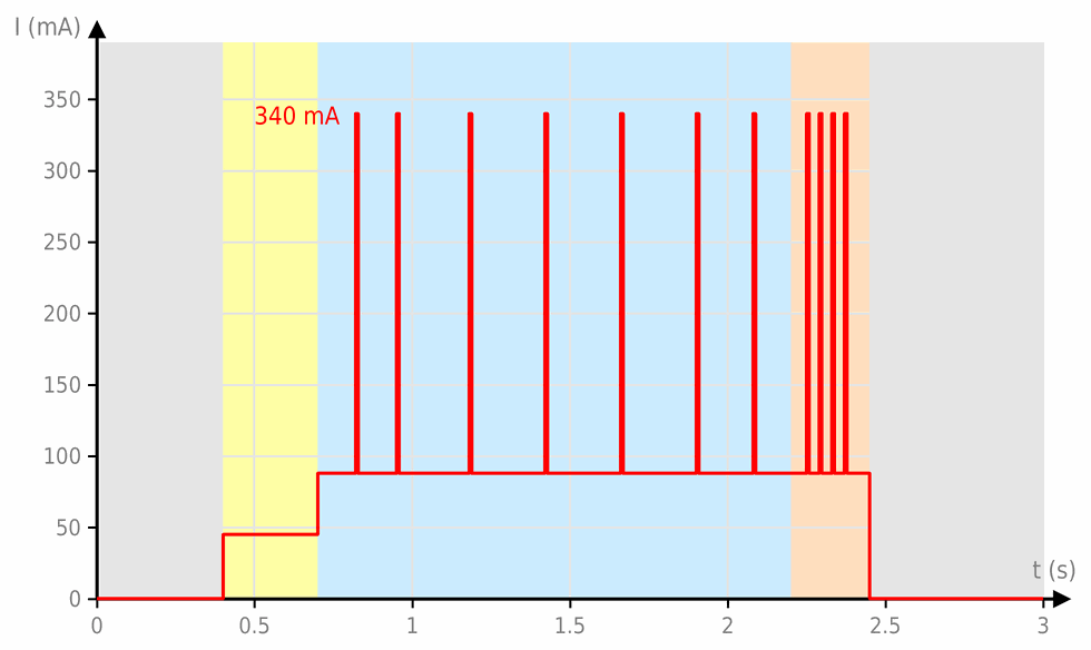
The graph is a model of one wake-up of an ESP32-S3: the currents are from the datasheet, and how long each step takes is an estimate, because it depends on the network. In deep sleep (grey) the chip draws only 7 µA. When it wakes up and starts (yellow), it draws about 45 mA, and while it connects to Wi-Fi and listens (blue), 88 mA. Every time it transmits something, the current jumps to 340 mA for a few milliseconds, and most of the peaks come while it sends data (orange). Because of these peaks, the voltage of a weak supply drops for a moment. If it drops below a limit, the chip resets itself, and the Serial Monitor shows Brownout detector was triggered. Then a shorter and thicker USB cable helps, or another USB port, or a capacitor of 100 to 470 µF between 3V3 and GND, as close to the module as possible.
Deep sleep is a mode in which only the clock and a small RTC memory work. The chip wakes up when a set time has passed or when a pin changes, and then the program starts again, from setup(). This program wakes up every 10 seconds and says how many times it has woken up. It keeps the number in the RTC memory, because the rest of the memory is wiped in sleep:
// Wakes up, says how many times it has woken up and sleeps for 10 seconds. ESP32 only (S3, C3 and the others).
RTC_DATA_ATTR int wakeUps = 0;   // the RTC memory stays on in deep sleep

void setup() {
  Serial.begin(115200);
  delay(1000);   // time for the Serial Monitor to reconnect
  wakeUps++;
  Serial.print("Wake-up number ");
  Serial.println(wakeUps);
  esp_sleep_enable_timer_wakeup(10ULL * 1000000ULL);   // 10 s, in microseconds
  Serial.println("Sleeping for 10 s.");
  Serial.flush();          // wait until the message has gone out before sleeping
  esp_deep_sleep_start();  // the chip goes to sleep; when it wakes up, the program starts again
}

void loop() {
  // never runs: after deep sleep the program starts again, from setup()
}
How long a device runs on batteries depends on how often it wakes up and how much the whole DevKit draws while it sleeps. The graph is calculated from the model in the graph above: one wake-up takes about 2 s and uses 190 mA · s, and the batteries hold 2000 mAh.
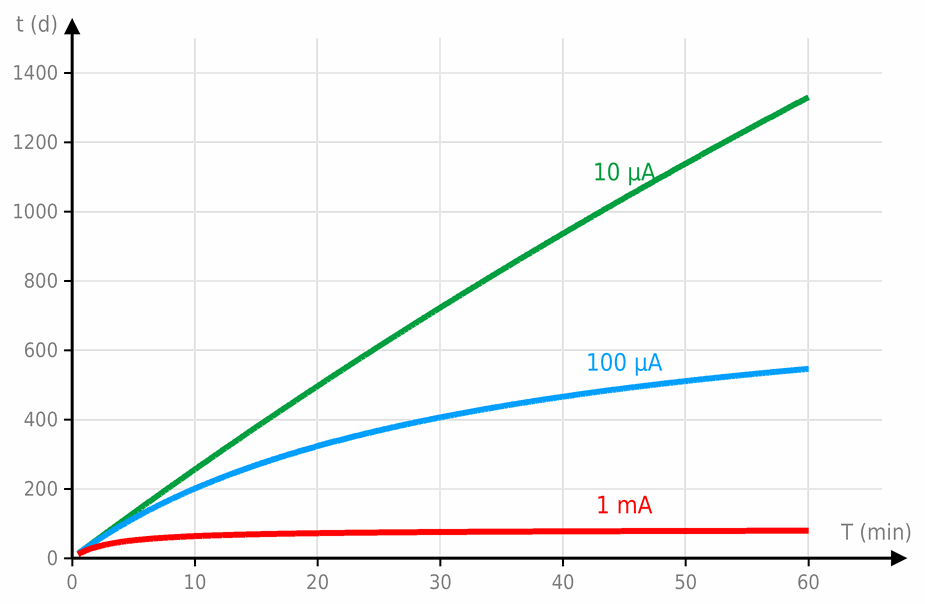
- If it wakes up every minute, the batteries last about 26 days, and it hardly matters how much the DevKit draws while it sleeps. Wi-Fi uses most of the current.
- If it wakes up every 10 minutes, they last 256 days when the DevKit draws 10 µA in sleep, but only 63 days when it draws 1 mA.
- If it wakes up once an hour, they last 1329, 546 or 79 days. Now the sleep uses most of the current.
The chip itself draws 7 µA in sleep, but the regulator, the USB-to-UART chip and the power LED on a DevKit can draw much more, even a few milliamps. That is why battery-powered devices use DevKits without a power LED and with a regulator that draws little current itself. Real batteries also slowly run down by themselves, so they last less than in the graph.
 What did we learn?
- The ESP8266 and the ESP32 are Espressif’s microcontrollers with Wi-Fi, and most ESP32 chips have Bluetooth too. They are programmed in the Arduino IDE, like an Arduino.
- The pins work at 3.3 V. They must never get 5 V, and one pin of an ESP32 gives at most 40 mA, of an ESP8266 12 mA.
- The chip is in a module with flash memory and an antenna, and the module is on a DevKit with a USB socket, a regulator and pins.
- The ESP32-S3 is the most powerful, for a camera, a display, sound and USB. The ESP32-C3 is small and cheap, for sensors and smart devices. The ESP8266 is the oldest and has no Bluetooth.
- The start-up pins decide how the chip starts, so don’t connect anything to them that pulls them to the other level at that moment.
- Wi-Fi uses a lot of current, with peaks up to 340 mA, so an ESP needs a good supply. In deep sleep the chip draws only a few microamps.