
Hall sensor
A Hall sensor feels a magnet without touching it: the A3144 switch, latches and linear sensors, wiring to an Arduino, and a steel ball over a magnet.
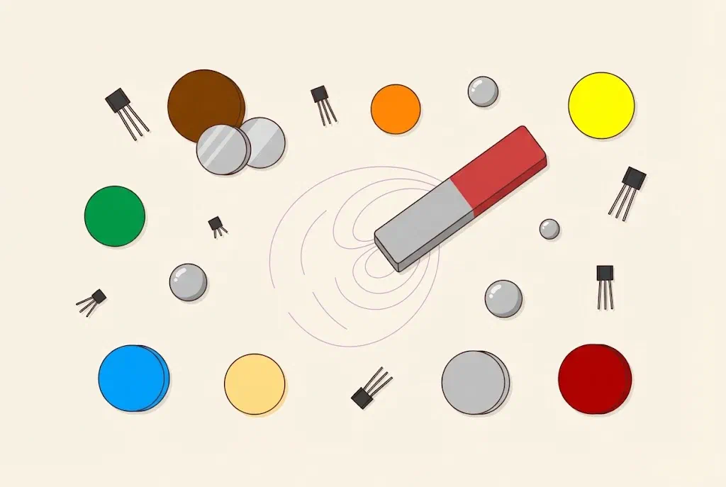
What is a Hall sensor?
Around every magnet there is a magnetic field. We can’t see it, but we notice it when a magnet pulls a nail or another magnet. The field is strongest next to the magnet’s poles, north (N) and south (S), and the further away we are, the weaker it gets.
A Hall sensor is a small chip that feels a magnetic field. It reports whether a magnet is near, without anything having to touch it. It is named after the American physicist Edwin Hall, who discovered in 1879 that a magnetic field pushes the current in a conductor slightly to one side.
Where we find them:
- a laptop has a magnet in its lid and a Hall sensor under the keyboard, so it knows when the lid is closed;
- many cars use Hall sensors to measure how fast the wheels and the engine turn;
- an electric scooter uses one to know how far you press the throttle;
- our pinball machine uses them to detect the ball in the lanes.
A Hall sensor does the same job as a reed switch, but it has no moving parts and no glass tube. It doesn’t wear out, doesn’t bounce and doesn’t break. In return it needs power, so it has three legs instead of two.
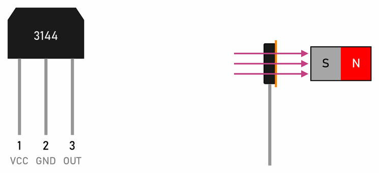
Our sensor, the A3144, is a small black case with three legs. The front has writing on it, and the legs, seen from the front, are:
- VCC: the supply, 5 V,
- GND: minus,
- OUT: the output, which reports to the Arduino.
The A3144 turns on when the south pole (S) of a magnet comes near its front, the side with the writing. The north pole doesn’t turn it on. If the sensor doesn’t react, turn the magnet round.
The micro:bit can feel a magnet
The micro:bit has a compass sensor, which also feels a magnetic field. The magnetic force (µT) block in the Input category gives the field's strength in microteslas. Show it on the display and bring a magnet near the micro:bit: the number shoots up. The Earth's magnetic field, which turns a compass needle, is only about 50 µT.
Three kinds of Hall sensor
- A switch (A3144): its output turns on when the field is strong enough, and off when the magnet goes away. We use it for the ball in the pinball machine.
- A latch (for example the US1881): a south pole turns it on, and it stays on even when the magnet goes away, until a north pole comes. With a ring of alternating poles it counts the turns of a motor or a wheel.
- A linear sensor (for example the 49E): it doesn’t only say yes or no, but how strong the field is. Without a magnet it gives about 2.5 V, more with one pole and less with the other. The Arduino reads it with
analogRead().
Strong magnets
Small neodymium magnets are very strong. Two of them leap at each other and can pinch a finger. Keep them away from phones and cards with a magnetic stripe. Never put magnets in your mouth: two swallowed magnets can pull together through the walls of the gut and cause serious injury.
The Hall sensor at the Arduino workshop
From here on, this page is for the Arduino workshop. We meet the Hall sensor with a magnet and a steel ball in the lesson Detecting the ball.
Wiring
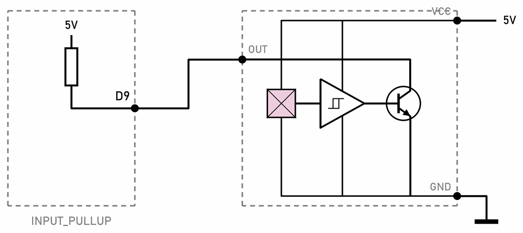
So the output needs a pull-up resistor, like a push button. We turn on the built-in one with pinMode(hallSensor, INPUT_PULLUP), and read the sensor like a button: LOW means a magnet or the ball, HIGH means nothing. If the wires to the sensor are long, add an external 10 kΩ pull-up resistor between OUT and 5V too.
- The A3144 needs at least 4.5 V, so we power it from the Arduino’s 5V. It doesn’t work on the micro:bit’s 3.3 V.
- A Hall sensor has no contacts, so it doesn’t bounce. The program reads it without debouncing.
- Its output can only be connected to GND, and the sensor needs power, so a Hall sensor can’t go into a switch matrix like a button. In the pinball machine the Hall sensors are therefore read by a 74HC165 chip.
Two switching points
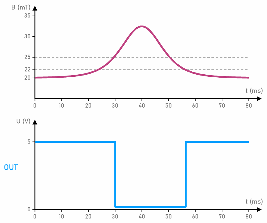
The sensor turns on at a stronger field than the one at which it turns off. The graph shows an example: the output drops to 0 V when the field rises to 25 mT, and goes back to 5 V only when it falls below 22 mT.
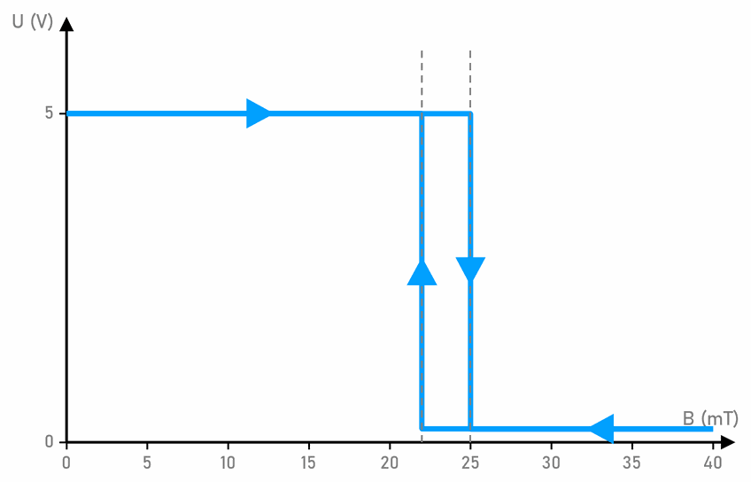
The switching points differ from sensor to sensor. For the A3144 the maker only guarantees that it turns on by the time the field rises to 35 mT, and turns off by the time it falls to 5 mT. That is why each module for the pinball machine is set up on its own.
A steel ball over a magnet
A steel ball isn’t a magnet, so a Hall sensor wouldn’t notice it on its own. That is why there is a magnet under the sensor, whose field is a little too weak for the sensor. When the ball comes over the sensor, the steel pulls the field lines towards itself and the field through the sensor gets stronger:
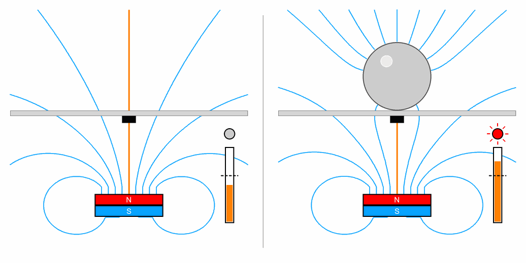
LOW, so it counts each pass once:// C++
int hall = digitalRead(hallSensor);
if (hall == LOW && lastHall == HIGH) { // the ball has just arrived over the sensor
passes = passes + 1;
}
lastHall = hall; // remember it for the next time round loop()
The board between the ball and the sensor must be thin. In the pinball machine it may be at most 2 mm thick, so we thin it from below there.
A linear sensor: how strong is the field?
The 49E linear sensor has the same three legs, but its output gives a voltage. Without a magnet that is about 2.5 V, half the supply, so analogRead() gives a number around 512. So the program first measures what the sensor gives without a magnet, and then prints the difference:
// C++
const int sensor = A0;                 // the output of a linear Hall sensor (49E)
const int THRESHOLD = 30;              // how much the number must change to turn the LED on

int resting = 0;                       // what the sensor gives without a magnet

void setup() {
  pinMode(LED_BUILTIN, OUTPUT);
  Serial.begin(9600);
  long sum = 0;
  for (int i = 0; i < 16; i++) {       // the average of 16 readings, while no magnet is near
    sum = sum + analogRead(sensor);
    delay(10);
  }
  resting = sum / 16;
}

void loop() {
  int field = analogRead(sensor) - resting;   // one pole gives positive numbers, the other negative
  Serial.println(field);

  if (abs(field) > THRESHOLD) {
    digitalWrite(LED_BUILTIN, HIGH);   // a magnet is near, whichever pole
  } else {
    digitalWrite(LED_BUILTIN, LOW);
  }
  delay(50);
}
Connect VCC to 5V, GND to GND, and the output to A0. Upload the program and open the Serial Plotter, as described on the Arduino IDE page. Bring a magnet near with one pole, then the other: the line goes up or down, and the closer the magnet, the further it goes. The abs() function takes the number without its sign, so the LED lights for both poles. The average in setup() is taken while no magnet is near, so bring the magnet close only once the program is running.
 What did we learn?
- A Hall sensor feels a magnetic field without touching. It has no contacts, so it doesn’t wear out or bounce.
- The A3144 has the legs VCC, GND and OUT. A magnet’s south pole facing the side with the writing turns it on.
- The output is connected to GND when the field is strong enough, so we read it with
INPUT_PULLUP, like a button:LOWmeans a magnet. - The sensor turns on at a stronger field than the one at which it turns off, so it doesn’t flicker.
- A steel ball over a magnet strengthens the field through the sensor. A linear sensor also reports how strong the field is.
Quick quiz
1. In what way is a Hall sensor better than a reed switch, and in what way not?
2. You bring a magnet near an A3144 and nothing happens. What do you try first?
3. Why do we use INPUT_PULLUP for the pin with a Hall sensor?
HIGH.4. Why don't we debounce a Hall sensor like a button?
5. A steel ball isn't a magnet. How does a Hall sensor notice it, then?
6. A linear sensor gives about 512 without a magnet. What do 600 and 420 mean?