
29 misconceptions about electronics
29 common misconceptions about electronics: does a resistor use up current, can LEDs share a resistor, what is ground, why can't an Arduino pin drive a motor?
Some ideas about electricity sound so logical that nobody checks them: a resistor uses up current, electrons race along at the speed of light, and a stronger charger pushes more current into a device. These misconceptions aren’t silly. They appear when you turn a useful simplification into a rule that is always true. The trouble is that you build on them, so when a circuit doesn’t work, you look for the fault in the wrong place.
Here are 29 common misconceptions, in order from the basics of current and voltage, through components and safety, to building a finished device.
Source and idea for this article
The idea for this article and 19 of the misconceptions come from the video 19 Common Electronics Myths Beginners Still Believe! on the YouTube channel Electronic Wizard.
In the comparison pictures, the left side (✗) shows the misconception and the right side (✓) shows how it really is.
Current and voltage
Misconception 1. Current gets used up in a resistor
The truth: A resistor doesn’t use up current, it limits it. As much current as goes into a resistor comes out of it. What a resistor uses up is energy: it turns it into heat, so it gets warm.
Imagine water flowing through a pipe with a narrow part. The narrow part reduces how much water flows, but the water doesn’t disappear in it: as much goes in as comes out.
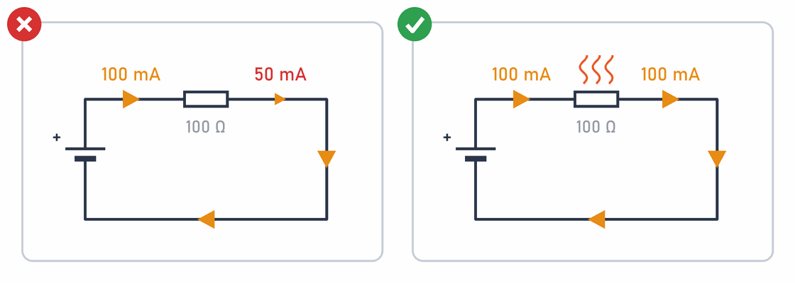
In more detail:
In a circuit without branches, the current is the same at every point. If you measure the current before and after the resistor with an ammeter, you get the same result (see Measuring current). The resistor decides how much current flows through the whole circuit, according to Ohm's law:
Misconception 2. Electrons and current flow in the same direction
The truth: In schematics, the current arrow goes from plus to minus. Electrons in a wire move the other way, from minus to plus. Both descriptions are right, they just describe different things. The direction of current was agreed long ago, before anyone knew about electrons, and the agreement has stayed.
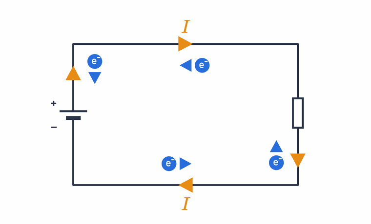
In more detail:
Conventional current flows from + to − through the outside of the circuit. It goes back to the 18th century, when Benjamin Franklin named one kind of charge positive and the other negative. The electron was only discovered in 1897. It turned out to have a negative charge, so in metals it moves the opposite way to the agreed direction of current.
For calculations it makes no difference: a negative charge moving to the left gives the same current as a positive charge moving to the right. That is why schematics and calculations always use conventional current. You can see it in the symbols too: the triangle in the diode and LED symbol points in the direction of the current through it, from anode to cathode, and so does the arrow on a transistor’s emitter.
What matters is to know which description you are using and to stick to it.
Misconception 3. Electrons travel through a wire at the speed of light
The truth: When you switch on a light, it comes on at once, but the electrons from the switch haven’t flown to the bulb. The wire is already full of electrons. When the battery pushes them at one end, they all move at the same moment, like marbles in a tube: push one in, and another one falls out of the other end straight away. The electrons themselves move through the wire more slowly than a snail.
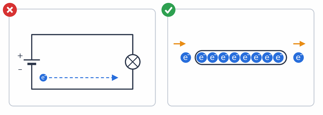
In more detail:
There are two different speeds:
- Signal speed is how fast a change (for example switching on) spreads along the wire. The change travels as an electromagnetic wave, close to the speed of light: in cables usually between 60 % and almost 100 % of the speed of light, depending on the insulation around the conductor.
- Drift velocity is the average speed of the electrons themselves through the conductor. It is very low:
Electrons in a conductor also move randomly and very fast, but in all directions, so this movement cancels out. The current is only their slow movement together. The key point: the bulb doesn’t wait for an electron from the battery to reach it.
Misconception 4. Current only takes the path of least resistance
The truth: When the path splits, current takes all the paths, not only the easiest one. More current goes the easy way and less the hard way. It is like children leaving school through two doors, a wide one and a narrow one: more children go through the wide door and fewer through the narrow one, but they use both.
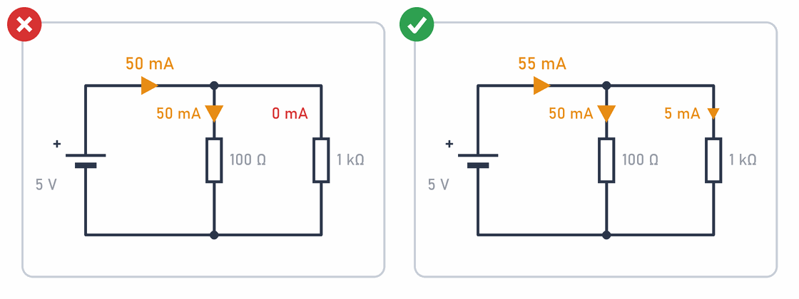
In more detail:
Branches in parallel have the same voltage, so you work out the current in each branch with Ohm’s law separately:
The saying current takes the path of least resistance is only roughly true, when one path is much easier than the others. That is exactly what happens in a short circuit: a 0.05 Ω wire connected across an LED and its resistor takes almost all the current, so the LED doesn’t light (see Short circuit). You can work out the total resistance of resistors in parallel with the resistors in parallel calculator.
Misconception 5. A power supply pushes all the current it can into a device
The truth: A charger might say 5 V 2 A. 2 A is the most the charger can give, not how much it will give. A device only takes as much current as it needs, just as you only drink as much from a big bottle as you are thirsty for. That is why you can power an Arduino or a micro:bit from a strong USB phone charger. But the voltage must match: a 12 V charger instead of a 5 V one would destroy the device.
In more detail:
The label 12 V / 5 A on a voltage source means: the source keeps the voltage at 12 V and can give at most 5 A. The load decides the current, according to Ohm’s law. A load with a resistance of 40 Ω on 12 V takes:
A load doesn’t always take the same current. A motor takes several times more current when starting or when it is stalled than when it spins freely. So you choose the power supply for the largest current, with a margin.
The exception is current sources, for example LED lighting drivers or a lab power supply with current limiting switched on. They keep the set current and adjust the voltage. For them, the current on the label really is the current through the load.
Misconception 6. Two batteries always give double the voltage
The truth: It depends on how you connect them. If you put them one after the other, the plus of one to the minus of the other (in series), the voltages add up: two 1.5 V batteries give 3 V. That is how the batteries in a micro:bit battery holder are connected. If you connect plus to plus and minus to minus (in parallel), the voltage stays 1.5 V, but the batteries last longer.
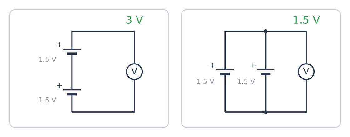
In more detail:
- In series: the voltages add up, and the same current flows through all the batteries. They last as long as one battery would. A 9 V battery is itself six small 1.5 V cells in series.
- In parallel: the voltage stays the same and the current is shared between the batteries. Together they can give more current and last longer.
Only connect identical batteries in parallel, and only if they are equally charged. If one is fuller than the other, current flows from it into the other one, with no resistor to limit it. With rechargeable batteries, especially Li-ion and LiPo, this is dangerous. Don’t mix an old and a new battery in series either: the weaker one runs flat first, and the others keep pushing current through it, so it can leak.
Misconception 7. A battery with more mAh is stronger
The truth: The number marked mAh tells you how long a battery can keep giving current, not how strong it is. It is like a bigger water bottle: you can drink from it for longer, but the water doesn’t flow any harder. How hard a battery pushes the current is given by its voltage, the number marked V. A 2000 mAh rechargeable battery lasts longer than the same kind of battery with 1000 mAh, but both have the same voltage.
In more detail:
mAh (milliamp-hour) is the unit for a battery’s capacity, the amount of charge it holds. A 2000 mAh battery can give 200 mA for about 10 hours:
The energy stored in a battery also depends on its voltage:
How much current a battery may give is a separate rating. For drone LiPo batteries it is the C rating: a 1000 mAh, 25C battery may give up to 25 A. A large capacity and a high current rating also mean large currents in a short circuit, so LiPo batteries have their own rules (see the Drone project).
Misconception 8. Ground, earth and 0 V always mean the same thing
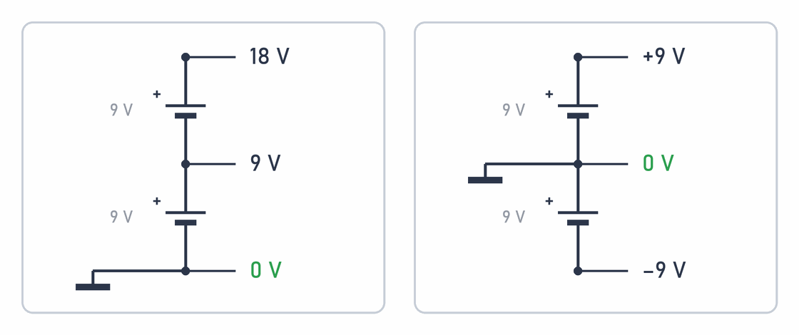
The truth: Voltage is always a difference between two points, like height. When you say something is 2 m high, you need to know whether you are measuring from the floor or from the table. In a circuit you pick one point as the floor. This point is called ground or GND. It is 0 V, and you measure all the other voltages from it. Earth is something else: a wire that is really connected to the earth, as in a mains socket.
In more detail:
The picture shows the same two 9 V batteries twice. On the left, ground is at the bottom, so the voltages are 0 V, 9 V and 18 V. On the right, ground is in the middle, so the same points are at −9 V, 0 V and +9 V. The batteries and the current are the same, only the point you measure from has changed. This is also how you get the ±9 V supply that some amplifiers need.
Three terms that often get mixed up:
- Ground (GND, 0 V) is the circuit’s common reference point, usually the minus of the power supply. It doesn’t have to be connected to the earth: the ground of an Arduino or a micro:bit running on batteries isn’t.
- Protective earth is the green and yellow wire in a mains cable and socket, connected to the earth. It protects people: if a fault connects a device’s metal case to mains voltage, the current flows into the earth and a fuse or a residual current device switches off. Protective earth is not a return path for the circuit’s current.
- Chassis ground is the device’s metal case. It may or may not be connected to the circuit ground or to earth.
In schematics, ground is often drawn as a thick line, as in the picture above, and earth as three lines that get shorter towards the bottom (see the symbols). But many schematics use either symbol for ground. So it isn’t enough to see the symbol: you need to understand what it is really connected to.
When two devices exchange signals, they must share a ground. That is why in the lesson Two traffic lights at a crossroads you connect the GND of both Arduinos.
Misconception 9. Logic 0 is always 0 V and logic 1 is always 5 V
The truth: The Arduino Uno works with 5 V and the micro:bit with 3.3 V. Both understand 0 and 1, but they don’t write a 1 with the same voltage. Also, a 1 isn’t one exact voltage but a whole range: everything above a certain voltage is 1, and everything below another one is 0. So don’t connect an Arduino output straight to a micro:bit pin: 5 V is too much for the micro:bit and can damage it.

In more detail:
A digital input has two thresholds, given in the chip’s datasheet:
- a voltage above the threshold VIH reads as 1 (
HIGH), - a voltage below the threshold VIL reads as 0 (
LOW), - in between, the result is undefined: the same voltage may read as 0 one time and as 1 the next.
For the microcontroller on the Arduino Uno (an ATmega328P on 5 V), 1 is anything above 3 V (0.6 · 5 V) and 0 anything below 1.5 V (0.3 · 5 V). For the micro:bit (3.3 V), 1 is above about 2.3 V and 0 below about 1 V. Many newer chips work with an even lower voltage, 1.8 V: sensors, memories and also some STM32 microcontrollers when they are powered from 1.8 V. For them, 1 is above about 1.3 V (0.7 · 1.8 V) and 0 below about 0.5 V (0.3 · 1.8 V). This means:
- The Arduino Uno reads a micro:bit output (3.3 V) as 1, but with little to spare.
- An Arduino Uno output (5 V) is too much for a micro:bit input: a micro:bit pin can take at most about 3.6 V. You need a voltage divider or a level shifter between them.
- Neither the Arduino Uno nor the micro:bit can reliably read the output of a 1.8 V chip as 1: the Arduino needs at least 3 V, and the micro:bit about 2.3 V. The other way round, 3.3 V or 5 V is usually too much for such an input. Here, too, you need a level shifter.
- An input that isn’t connected to anything (floating) is often right in the undefined range. That is why a pull-up or pull-down resistor is needed (misconception 10).
The old serial port on computers, RS-232, shows that it is all a matter of agreement: in it, 1 is a voltage between −3 and −15 V, and 0 is between +3 and +15 V. Such a signal connected straight to an Arduino pin would damage it.
Misconception 10. An unconnected input reads 0
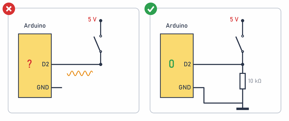
The truth: A pin that isn’t connected to anything doesn’t read 0, it reads at random: sometimes 0, sometimes 1. It picks up interference from its surroundings like an aerial, so it changes even when you just bring your hand near it. That is why you connect a button together with a resistor that holds the pin in a known state while the button isn’t pressed.
In more detail:
A digital input has a very high resistance, so almost no current flows into it. That is good, because the input doesn’t load the signal, but it also means an unconnected pin has no defined voltage: the slightest interference moves it, for example from a mains cable or a hand nearby. The pin is said to be floating, and it is often right in the undefined range between 0 and 1 (misconception 9).
The solution is a resistor that pulls the pin into a known state:
- A pull-down resistor (for example 10 kΩ) connects the pin to GND, and the button connects the pin to 5 V. The button gives 0 when released and 1 when pressed. This is the circuit in the picture, and you also use it in the lesson Two traffic lights at a crossroads.
- A pull-up resistor connects the pin to 5 V, and the button connects the pin to GND. The button gives 1 when released and 0 when pressed. The Arduino has built-in pull-up resistors, which you switch on with
pinMode(pin, INPUT_PULLUP); then no external resistor is needed.
The resistor must be large enough that no big current flows through it when the button is pressed (5 V / 10 kΩ = 0.5 mA), and small enough to overpower interference.
Misconception 11. analogWrite() gives a real analogue voltage
The truth: An Arduino Uno can’t make 3 V on a pin. It can only switch 5 V on and off, but so fast that an LED looks dimmer, as if it were getting less current. This is called PWM. Your eye doesn’t see the flicker, only the average brightness.
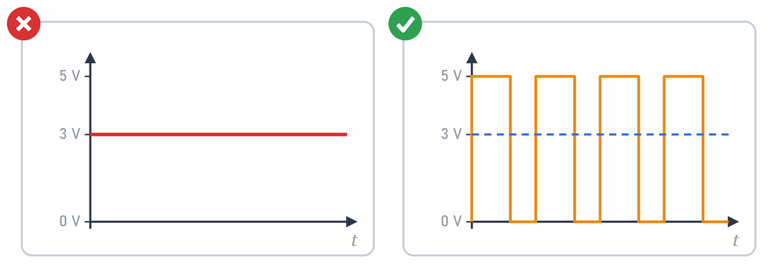
In more detail:analogWrite(9, 153) doesn’t give 3 V. The pin switches between 0 V and 5 V about 490 times a second (about 980 times on pins 5 and 6), and the number from 0 to 255 sets what part of the time the pin is on. This is the duty cycle. For 153 that is 60 % of the time, so the average voltage is:
PWM only works on the pins marked ~ (on the Arduino Uno: 3, 5, 6, 9, 10 and 11). For a real analogue voltage you need an RC filter, which smooths out the pulses, or a digital-to-analogue converter (DAC).
Components
Misconception 12. Real components behave like ideal ones
The truth: Exercises usually say: the battery has 9 V and a wire has no resistance. That is a simplification, like drawing a road on a map as a straight line. A real battery has a bit more or a bit less, and when it drives a motor, its voltage drops. A 220 Ω resistor might measure 215 or 228 Ω. These components aren’t broken; that is what real components are like.
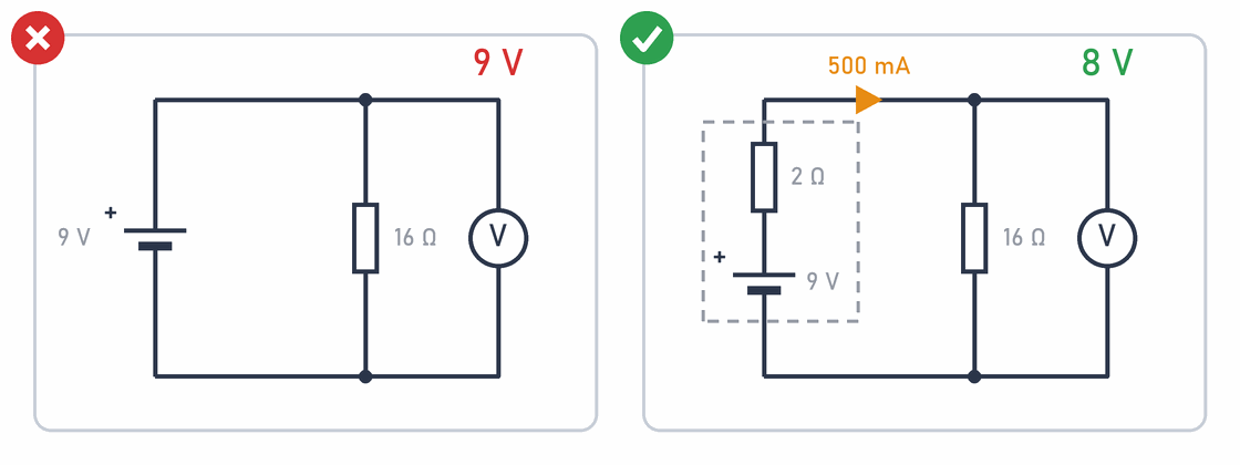
In more detail:
A real battery is described as an ideal voltage source E with a small internal resistance Ri in series. When current flows, part of the voltage is lost across the internal resistance:
A few more examples:
- Resistors have a tolerance: a gold band means ±5 % and a brown one ±1 %. A 220 Ω ±5 % resistor may measure anything from 209 to 231 Ω.
- Electrolytic capacitors often have a tolerance of ±20 %, and they lose capacitance as they age. A charged capacitor slowly discharges on its own.
- A silicon diode doesn’t always drop exactly 0.7 V: depending on current and temperature it is roughly 0.5 to 0.8 V. A red LED drops about 2 V, and a blue or white one about 3 V.
- Wires and contacts on a breadboard have a small resistance, which grows when a contact is worn.
If a measured resistance or capacitance differs from the marking, first compare it with the tolerance and the measuring conditions. The ideal model is a good first estimate, not a promise from the manufacturer.
Misconception 13. An LED has a resistance you can calculate with Ohm’s law
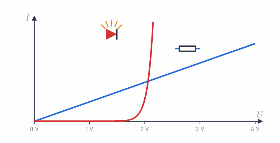
The truth: An LED isn’t a resistor. While the voltage is low, almost no current flows through it. When the voltage passes a certain limit (about 2 V for a red LED), the current shoots up. That is why an LED always needs a resistor to limit the current.
In more detail:
In a resistor the current rises steadily with the voltage (blue line): double the voltage, double the current. An LED (red curve) is different. Below the forward voltage UF the current is almost zero, and above it a very small rise in voltage means a big change in current. So an LED has no single fixed resistance that could be put into Ohm’s law.
That is why the resistor sets the LED’s current. You subtract the LED’s voltage from the supply voltage, and the rest of the voltage is across the resistor:
Misconception 14. The resistor has to be on the plus side of the LED
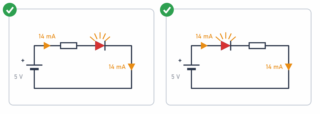
The truth: It makes no difference. The resistor and the LED are connected one after the other, so the same current flows through both. The resistor limits it just as well before the LED as after it. All that matters is that the LED is the right way round: the longer leg towards plus.
In more detail:
In a series circuit the current is the same at every point (misconception 1), and the supply voltage is shared: about 2 V across the LED and about 3 V across the resistor, whatever the order. That is why both circuits in the picture give the same current of about 14 mA.
In practice, people still put the resistor on the same side every time, to keep things tidy. When several LEDs share a common GND, the resistor usually goes on the pin side. On a breadboard, pick one way and stick to it, because that makes mistakes easier to find (see Tidy wiring).
Misconception 15. Several LEDs can share one resistor
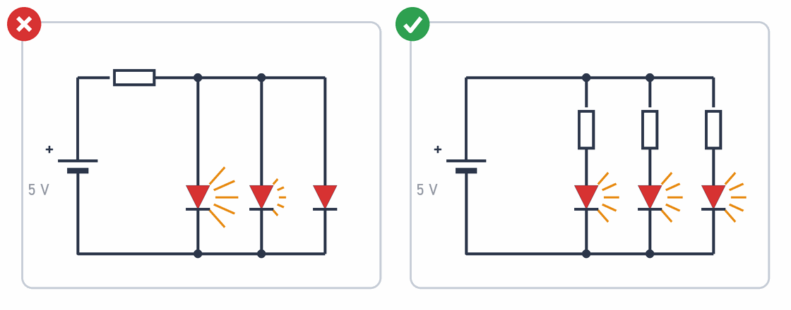
The truth: If you connect several LEDs in parallel to one resistor, one will shine brighter and the others dimmer or not at all. That one gets almost all the current and may burn out, and then the current moves on to the next one. Every LED needs its own resistor.
In more detail:
Not even two LEDs of the same colour have exactly the same forward voltage: they differ by tens or even hundreds of millivolts. Because of the LED’s steep curve (misconception 13), this small difference means a big difference in current: the LED with the lowest voltage takes most of the current. As it warms up, its voltage drops further (misconception 26), so it takes even more. LEDs of different colours (red about 2 V, blue about 3 V) can’t share a resistor at all: the blue one hardly lights.
So every LED gets its own resistor. The other option is to put the LEDs in series with one resistor, if the supply voltage allows it. Two red LEDs (2 × 2 V) with a resistor on 5 V leave only 1 V for the resistor, and three would no longer light.
Misconception 16. Only the resistance matters in a resistor
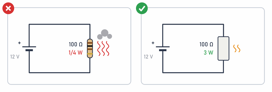
The truth: A resistor has another important number: its power rating, how much heat it can handle. The small resistors you use with LEDs are usually rated 1/4 W. For an LED that is more than enough. But if you send a large current through a small resistor, it overheats, smokes and burns out, even though its resistance is right.
In more detail:
A 100 Ω resistor is connected to 12 V. The current through it is:
For comparison, a 220 Ω resistor with a red LED on 5 V: it has about 3 V across it, the current is about 14 mA, and the power is 3 V · 0.014 A ≈ 0.04 W, six times less than 1/4 W. You can work out the resistor for an LED with the LED resistor calculator, and there is more about resistor sizes in Resistors and power.
A power rating doesn’t mean the resistor stays cool. A resistor working close to its rating can be hotter than 100 °C, so it needs space and air around it.
Misconception 17. A bigger capacitor is always better
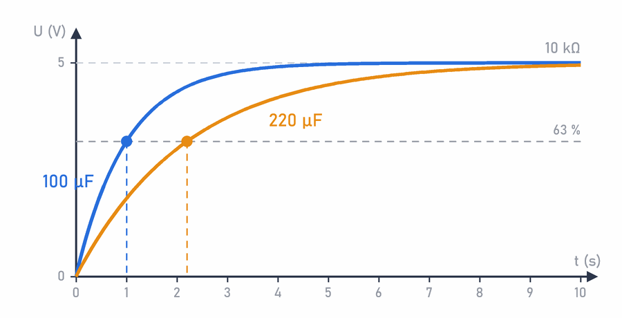
The truth: A capacitor is like a bucket that fills up with current. A bigger bucket takes longer to fill and longer to empty. If you swap the capacitor in a blinking LED circuit for a bigger one, the LED will blink more slowly. A bigger capacitor isn’t better, just different.
In more detail:
When a capacitor charges through a resistor, the charging speed is set by the time constant:
- 10 kΩ · 100 µF = 1 s,
- 10 kΩ · 220 µF = 2.2 s.
So in a timer, a filter or a blinking circuit, changing the capacitor changes the time or the frequency. Bigger isn’t always better in a power supply either: a large capacitor draws a large current while it charges at switch-on.
A capacitor has two important ratings: its capacitance (for example 100 µF) and its maximum voltage (for example 16 V). The voltage rating must be higher than the voltage in the circuit, with a margin. A higher voltage rating does no harm, but the capacitor is usually bigger. When you replace one, also watch the polarity: an electrolytic capacitor connected the wrong way round or to too high a voltage can swell and burst (see Electrolytic capacitors). You can decode the markings on capacitors with the capacitor calculator.
Misconception 18. A coil is just a different kind of resistor
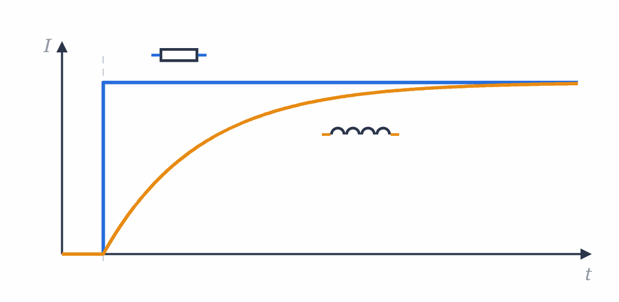
The truth: A coil is wire wound into a loop. When current flows through it, it becomes a magnet (an electromagnet). A coil doesn’t like changes in current: like a heavy shopping trolley, it takes time to get it moving, and once it is moving, it is hard to stop suddenly. Relays, motors and speakers all work with coils.
In more detail:
A resistor turns electrical energy into heat. A coil stores it in a magnetic field and resists changes in current. Its main property is inductance L, measured in henries (H). The voltage across a coil depends on how fast the current changes:
A real coil also has the resistance of its wire, but that isn’t the same as inductance. If you measure a relay coil with a multimeter, it might show 70 Ω, but that tells you nothing about what happens when you switch it off.
And switching off is the most dangerous moment. The current through the coil can’t stop suddenly, so ΔI/Δt is very large, and for a moment the coil produces tens or even hundreds of volts. This can destroy the transistor or pin that controls the relay or motor. That is why you put a flyback diode across a relay coil or a motor, as in the schematic in misconception 25.
Misconception 19. Decoupling capacitors aren’t needed
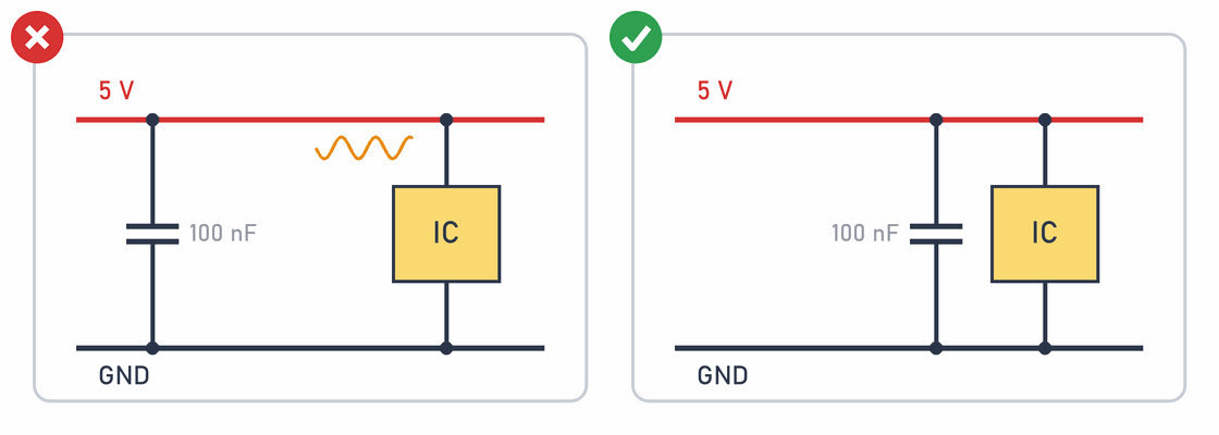
The truth: Sometimes a chip suddenly needs a lot of current for a split second. A small capacitor right next to the chip is like a water bottle a runner carries: they don’t need to run to the tap, they can drink straight away. Without it, a chip sometimes works and sometimes behaves strangely or restarts on its own.
In more detail:
A decoupling (bypass) capacitor, usually a 100 nF ceramic one, goes as close as possible to each chip’s power pins (VCC and GND). When a chip suddenly draws current, for example when it switches all its outputs at once, the long wires to the power supply can’t deliver it quickly enough. Wires have resistance and inductance, so the voltage at the chip dips or rings for a moment. The capacitor next to the chip supplies that current from close by. That is why a capacitor at the other end of the breadboard doesn’t help much: there are long wires between it and the chip again.
- The Arduino Uno and the micro:bit already have decoupling capacitors on the board. You need them when you put a separate chip on a breadboard, for example a 74HC08 logic gate.
- Motors and relays cause interference on the power supply. If the Arduino restarts every time a motor switches on, the cause is often a voltage dip. A separate supply for the motor, a common GND and capacitors all help.
- The value and position of decoupling capacitors are given in the chip’s datasheet.
A circuit that works on the bench without them doesn’t prove they aren’t needed. These problems come and go and are hard to reproduce, which makes them the hardest faults to find.
Misconception 20. Only the current matters for switches and relays
The truth: When a switch turns the current off, a spark jumps between its contacts for a moment. A switch has to be built so it can put that spark out. That is why a switch or a relay is marked with both current and voltage, separately for different kinds of voltage. The same switch can safely switch one thing and be too weak for another. In the workshop you only switch low voltages with switches and relays.
In more detail:
Relay modules for the Arduino are often marked 10A 250VAC and 10A 30VDC. The same relay can break 10 A at an alternating voltage (AC) of up to 250 V, but at a direct voltage (DC) only up to 30 V. Why?
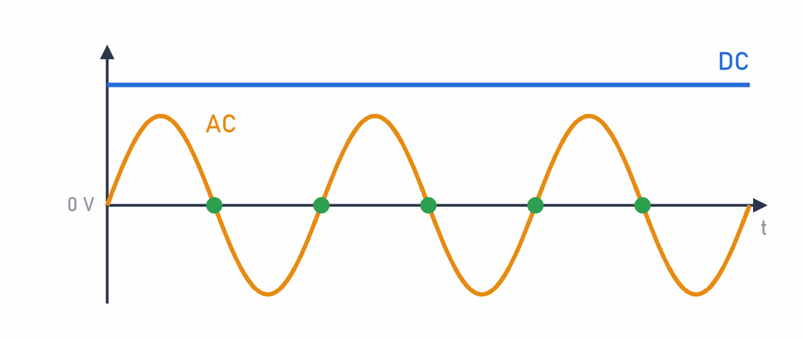
When the contacts separate, an electric arc forms between them. Alternating mains voltage at 50 Hz passes through zero 100 times a second (the green dots in the picture), so the arc goes out by itself. Direct voltage never drops to zero, so the arc can keep burning, melting and wearing the contacts. That is why the DC ratings are lower.
The ratings apply to a particular kind of load. Motors and lamps draw several times more current at switch-on, and coils produce a high voltage at switch-off (misconception 18), so a switch can handle less of them. When choosing one, look at the whole table in the datasheet, not just the biggest number.
A relay doesn't make mains voltage safe
A 250VAC marking only means the relay can break such a voltage. It doesn't mean a circuit that uses it is safe to touch. In the workshop you only use relays with low voltages, and you never work with mains voltage.
Safety and protection
Misconception 21. A large current isn’t dangerous if the voltage is low
In more detail:
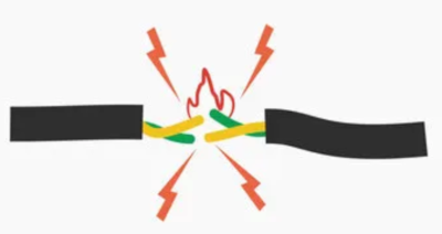
For an electric shock, voltage is what matters: skin has a high resistance, so at a low voltage very little current flows through the body. For heating a conductor, the current through it is what matters:
- A 9 V battery touching steel wool can set it on fire. That is why 9 V batteries are stored with a protective cap.
- A car battery has only 12 V, but in a short circuit it gives hundreds of amps. A spanner that connects its terminals glows red hot.
- Li-ion and LiPo batteries (in phones and drones) can swell up and catch fire in a short circuit.
So even low-voltage circuits need thick enough wires, solid connections and protection. There is more about this on the Short circuit page.
Misconception 22. When a device is switched off, it is safe
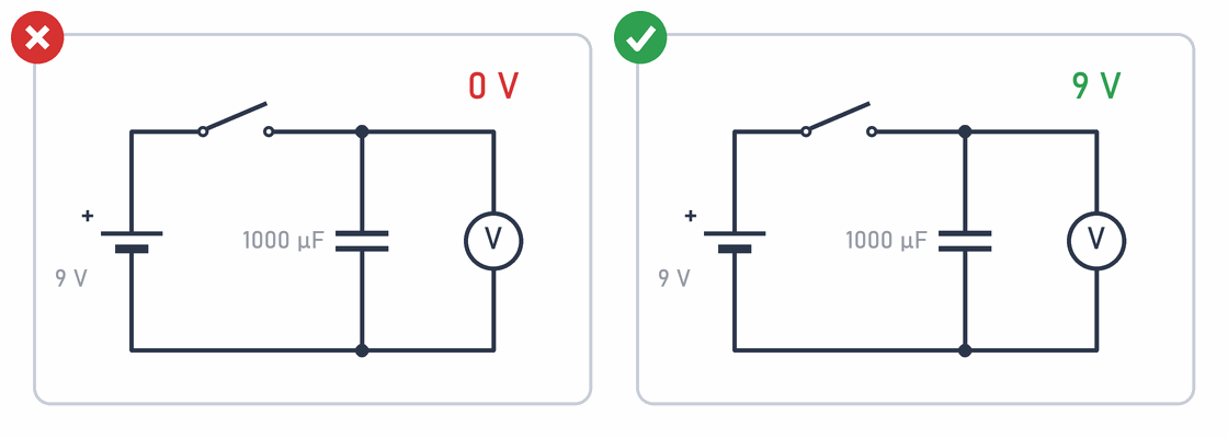
The truth: Some parts keep their energy even after switching off. A capacitor is like a small tank: it fills up while the device is on and stays full even when you take the battery out. So don’t touch the legs of large capacitors with your fingers or with metal, even when the circuit is off.
In more detail:
After switching off, a capacitor keeps the voltage it was charged to and discharges slowly, through its own leakage and through whatever is connected to it. The energy stored in a capacitor is:
In devices that plug into the mains (power supplies, camera flashes, microwave ovens), capacitors stay charged to hundreds or even thousands of volts long after the device is unplugged. So never open such devices.
Misconception 23. Static electricity can’t damage electronics
The truth: When you touch a door handle in winter and feel a little zap, that is static electricity. Such a spark doesn’t hurt you, but it can damage a chip, even a spark you don’t feel at all. That is why, before you start, you touch a metal radiator, hold boards by their edges and don’t touch the legs of chips.
In more detail:
Walking on a carpet or taking off a woolly jumper can charge your body to several thousand volts. You only feel a spark from about 3000 V, but sensitive chips can be damaged by a few hundred volts or even less. The spark’s current is brief and small, so it doesn’t hurt you, but it breaks through very thin insulating layers inside the chip. The damage isn’t always visible at once: the chip may keep working, but worse, or fail much later.
Protection against static electricity (ESD, electrostatic discharge):
- Before you start, touch earthed metal, for example a radiator.
- Hold boards by their edges and don’t touch the legs of chips or the connectors.
- Keep chips and modules in antistatic bags, the silvery or pink ones.
- Professional workshops use an antistatic wrist strap and mat connected to earth.
The pins of the Arduino and the micro:bit have protection diodes that can handle small sparks, but they aren’t indestructible.
Misconception 24. A fuse protects against every fault
The truth: A fuse reacts to only one thing: too much current. When the current gets too large, the fuse blows and breaks the circuit. If a device breaks in some other way, for example a wire comes off or an LED burns out, the fuse doesn’t notice and stays intact. And when a fuse blows, it means there is a fault somewhere that needs to be found.
In more detail:
A fuse protects wires, the power supply and the surroundings from overheating and fire. It doesn’t protect sensitive parts: a transistor, an LED or a microcontroller pin burns out in a split second, faster than the wire in the fuse can melt. A fuse doesn’t react at once either. The larger the current, the faster it blows, and a current just above the rating can flow for a long time and heat the circuit without blowing the fuse. That is why there are fast and slow-blow fuses for different uses.
Many faults don’t increase the current at all: a broken connection, a bad contact, a wrong program, a faulty sensor. Then the fuse is intact, but the device doesn’t work.
When a fuse blows:
- Find the cause: a short circuit, an overload or a faulty component.
- Replace the fuse with a new one of the same rating and type. A multimeter set to measure current has a fuse like this too (see Measuring current).
Never fit a bigger fuse, or a wire or foil instead of a fuse. Then there is no protection left, and the next fault can start a fire.
Misconception 25. A microcontroller pin can drive any load directly
The truth: An Arduino pin can light an LED, but it can’t run a motor. A pin is like a person pressing a switch: it gives the signal, but it can’t carry a heavy load by itself. A motor, a relay or a bright lamp needs a helper, a transistor, which switches the current from a stronger power supply.

In more detail:
An Arduino Uno pin can give about 20 mA (the absolute maximum is 40 mA), and all the pins together about 200 mA. A small motor takes a hundred to a few hundred mA when running, and more when starting. A 5 V relay coil takes 70 to 90 mA. Connected straight to a pin, a load like that overloads the pin and can damage it for good, and the motor’s interference can restart the microcontroller.
The correct circuit (on the right in the picture):
- The pin controls the base of an NPN transistor through a resistor (for example 1 kΩ). Only about 4 mA flows through the pin.
- The transistor switches the motor’s current from the power supply.
- The diode across the motor protects the transistor from the voltage produced at switch-off (misconception 18).
- The motor is best powered from a separate supply, with a common GND for all parts.
For larger currents, MOSFETs and ready-made motor drivers are used, but the principle is the same. In the lesson Arduino - step by step you control an LED with a transistor driven by an Arduino pin. The rules for pins are also on the Short circuit page.
Misconception 26. Temperature only matters when a component burns out
The truth: Heat changes how parts work long before they break. A phone in the cold shows an empty battery sooner, and a hot computer processor slows down so it doesn’t overheat. That is why parts that get warm need air around them.
In more detail:
Almost every electrical property depends on temperature:
- The voltage across a silicon diode or an LED drops by about 2 mV for every degree it warms up.
- Batteries give less current and less energy in the cold.
- The resistance of copper wire rises by about 0.4 % per degree.
- A thermistor uses this on purpose: its resistance changes a lot with temperature, so it works as a temperature sensor.
You can calculate heat. A 7805 linear voltage regulator that makes 5 V from 12 V with a current of 0.5 A turns the voltage difference into heat:
A heatsink doesn’t reduce the heat produced, it only makes it easier to get rid of, and only if it is firmly attached and has air around it. Sometimes the better solution is to make less heat, for example with a switching regulator instead of a linear one.
From schematic to device
Misconception 27. If the circuit doesn’t work, the schematic is wrong
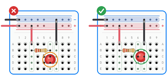
The truth: A schematic is like a recipe. If a cake goes wrong, the recipe may be fine, but the egg stayed in the fridge or the salt and the sugar got mixed up. When a circuit doesn’t work, the fault is usually in the wiring: a leg in the wrong row of the breadboard, an LED the wrong way round or a wire that isn’t making contact.
In more detail:
A schematic shows how the parts should be connected, not how they really are. Before you suspect the schematic, check:
- the connections, row by row, ticking off each one on a printed schematic,
- bad contacts on the breadboard and wires that have come out,
- component values: 220 Ω and 22 kΩ resistors differ in only one band,
- the pin order: BC547 and 2N2222 transistors in the same package have their legs in reverse order (BC547: C, B, E; 2N2222: E, B, C), so swapping one for the other without rewiring doesn’t work,
- the power supply: is it on, does it have the right voltage, and is GND shared,
- components that might be faulty.
Measure the power supply with a multimeter first, then follow the signal from the input to the output. There are more tips in Common mistakes and When the circuit doesn’t work.
Misconception 28. A simulation predicts exactly how a circuit behaves
The truth: A simulator, like the one in MakeCode, is great for trying out an idea. But it doesn’t know that a wire has come out, that the battery is weak or that the LED is the wrong way round. So always try a program that works in the simulator on a real micro:bit or Arduino too.
In more detail:
A simulator calculates the behaviour of the model you give it. If the model doesn’t include something, the result won’t show it either. Often missing are the resistance of contacts and wires, the battery’s internal resistance, interference, heating, component tolerances and sometimes the current limit of the pins.
It can also work the other way round: a simulation shows a problem that isn’t there in the real circuit, because of wrong settings or a model that is too simple.
A simulation is an excellent tool for understanding and checking an idea, but it doesn’t replace measuring the real circuit.
Misconception 29. Once a circuit has worked, the job is done
The truth: When a circuit works for the first time, that is a big success, but it is only the beginning. A paper plane that flew well once won’t necessarily fly in the wind. A real device has to work every time: when you carry it in your bag, when the battery is half empty and when someone presses the wrong button.
In more detail:
A successful test on the bench proves that the circuit can work under those conditions. A prototype confirms the idea, while a reliable device has to cope with the conditions it will really be used in:
- a different power supply: a weaker battery, a longer cable, another charger,
- interference from motors, relays and other devices,
- temperature: sunshine, cold, a closed box with no air,
- vibration and being carried around: breadboard connections work loose, which is why finished devices are soldered,
- users who do unexpected things: press a button twice, press it while the device is starting up, or pull out a cable.
So test a finished device for longer and under different conditions, and deliberately try to break it. Every fault you find before the user does is a good fault. You can see how a breadboard circuit becomes a finished device in our projects.
From simplification to real circuit
Most of these misconceptions appear when you turn a useful simplification into a rule that is always true. For first calculations you assume an ideal wire, a constant battery voltage or a diode drop of exactly 0.7 V. That is fine, as long as you don’t forget that it was an assumption.
So the most important habit in electronics is checking: checking assumptions, datasheets, connections and measurements. When a real circuit doesn’t behave like your model, that isn’t just an obstacle. It is a chance to find out what the model missed and to build the next circuit better.
 What did we learn?
- A resistor doesn’t use up current, it limits it. Energy is turned into heat in it.
- Electrons move slowly through a wire, while a change spreads at almost the speed of light.
- Current flows through every branch, not only the one with the least resistance.
- Batteries in series add up their voltage, and in parallel they last longer. mAh tells you how long a battery lasts, not how strong it is.
- A device takes as much current as it needs, but the source’s voltage must match the device.
- Ground (0 V) is the point you choose as the reference. Earth is something else.
- Logic levels are voltage ranges, and they differ between devices (5 V and 3.3 V). An unconnected input reads at random, so it needs a pull-up or pull-down resistor.
analogWrite()gives PWM, fast switching on and off, not a steady voltage.- An LED has no fixed resistance. Every LED needs its own resistor, and it doesn’t matter whether it goes before or after the LED.
- Real components have tolerances and depend on temperature, and a resistor also has a power rating.
- A microcontroller pin gives the signal, and a transistor switches motors and relays.
- A fuse protects against too much current, not against every fault.
- A capacitor can stay charged after switching off, and static electricity can damage a chip.
- A schematic, a simulation and the first successful test are the start of checking, not the end of it.
Short quiz
1. A current of 20 mA goes into a resistor. How much current comes out of it?
2. Can you power an Arduino from a USB phone charger marked 5 V 2 A, if the Arduino needs 50 mA?
3. Why shouldn't you connect an Arduino Uno output straight to a micro:bit pin?
4. Why do you put a diode across a motor or a relay coil?
5. The fuse in a device is intact, but the device doesn't work. What does that mean?
6. Why are the grounds of two Arduinos connected when they exchange signals?
7. Can you put an LED's resistor between the LED and minus, instead of between plus and the LED?
8. Three LEDs are connected in parallel to one resistor. One shines brightly and the other two hardly at all. Why, and how do you fix it?
9. A button connects pin D2 to 5 V. When the button isn't pressed, the Arduino reads sometimes 0 and sometimes 1. What is missing?
INPUT_PULLUP.10. You have two 1.5 V batteries. How do you connect them to get 3 V, and how to make them last longer?
More advanced questions
11. A 47 Ω resistor is connected to 5 V. Is a 1/4 W resistor enough?
12. A relay is marked 10A 250VAC and 10A 30VDC. Can you use it to break 10 A at a direct voltage of 48 V?