
Multimeter
How a multimeter works: its parts, the symbols on the dial, reading the display, testing continuity, measuring voltage and current, and common mistakes.
What is a multimeter?
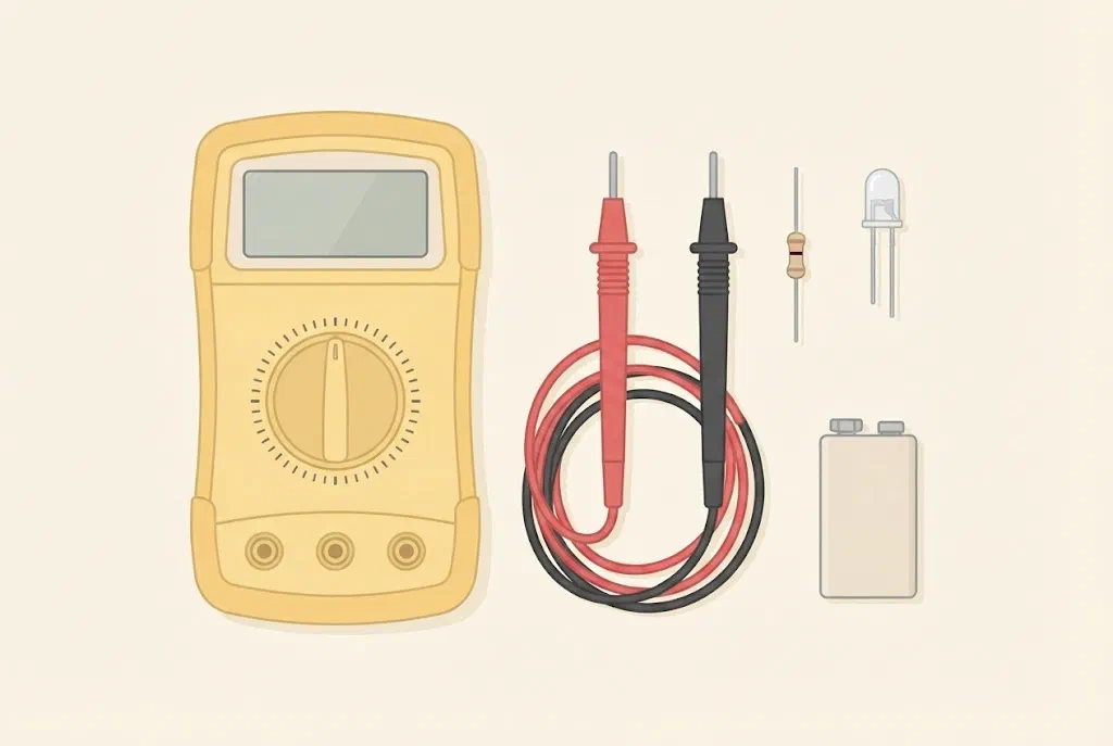
A multimeter is an instrument with several measuring devices in one case. We use it to measure voltage, current and resistance, and to check whether a connection is closed.
A multimeter is an electricity detective’s tool. When a circuit doesn’t work, we don’t have to guess: we measure and find out where the problem is. In the lesson Electricity detectives we test materials with an LED tester. A multimeter does the same job, but it also tells us how much.
Parts of a multimeter
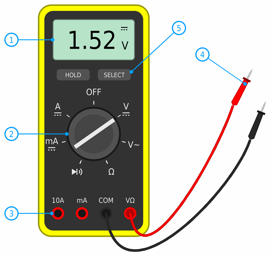
- The display shows the measured value.
- The dial (rotary switch) chooses what we measure. In the OFF position the multimeter is switched off.
- The sockets are the holes we plug the probes into. There are usually three or four: COM, VΩ, mA and 10A.
- The probes are two leads with pointed tips: a black one and a red one. The black one always goes in the COM socket.
- The buttons have various jobs. HOLD keeps the number on the display, and SELECT chooses between two functions on the same dial position.
Symbols on the dial
| Symbol | What it measures | Do we use it? |
|---|---|---|
| V⎓ (straight line) | DC voltage: batteries, Arduino, micro:bit | yes, most often |
| V~ (wavy line) | AC voltage | no, because there is no AC voltage at the workshop |
| Ω | resistance | yes, with the power off |
| speaker or diode symbol | continuity: is the connection closed? | yes, with the power off |
| A⎓, mA⎓ | DC current | yes, with the leader |
| OFF | switched off | always after measuring |
Some multimeters have other symbols too, for example for capacitors or temperature. If you don’t know what a symbol means, ask the leader.
How to read the display
- Number and unit: look at the number and the unit next to it. 220 when measuring resistance can be 220 Ω, and 2.20 with the kΩ symbol is 2200 Ω.
- Decimal point: the display shows a point, just as we write it in English: 1.52 on the display is 1.52 V.
- OL, or 1 on the left: the value is too large for the selected range. When measuring resistance it means that the probes aren’t connected to anything, or that the connection is broken.
- A minus before the number: the probes are the wrong way round, the red one is on minus. This isn’t a fault: the multimeter isn’t damaged, it only shows that the voltage is reversed.
- The last digit jumps: that is normal. Write down the value that appears most often.
- A battery icon: the battery in the multimeter is running out, so the measurements are no longer accurate.
Detective mode: continuity
The simplest measurement is continuity. The multimeter beeps when its two probes are connected: directly, or through a wire, a switch or another conductor. This lets us check:
- whether a wire is whole or broken somewhere,
- whether a switch or a button connects when we press it,
- whether two holes of a breadboard are connected (see Breadboard),
- whether there is a short circuit somewhere.
How we measure:
- Switch off the circuit’s power. Continuity is always measured with the power off.
- Plug the black probe into COM and the red one into VΩ.
- Turn the dial to the speaker or diode symbol.
- Touch the probe tips together. The multimeter should beep. Now you know it works.
- Touch the two ends of what you are checking with the probes. If it beeps, the connection is closed. If it doesn’t, the connection is broken.
How to find a short circuit with a multimeter is explained on the Short circuit page.
Rules for using a multimeter
- Never measure anything in a mains socket or on a device that plugs into one. Mains voltage (230 V) can kill.
- First choose what you measure and plug in the probes, and only then touch the circuit.
- Don't turn the dial while the probes are touching the circuit.
- Measure resistance and continuity only when the power is off.
- The probe tips are sharp. Don't point them at yourself or at others.
- Measure current only with the leader. After measuring current, put the red probe back in VΩ.
- When you have finished, turn the dial to OFF, so the multimeter's battery doesn't run down.
Common mistakes
- The red probe was left in the mA or 10A socket, and we measure voltage. The multimeter is then connected like a wire between plus and minus: that is a short circuit. The fuse in the multimeter blows and the battery gets hot.
- We measure resistance in a circuit that is switched on. The result is wrong, and the multimeter can be damaged.
- The dial is on V~ instead of V⎓. On a battery the display shows a strange number or zero.
- Your fingers hold both tips while you measure a large resistance. The multimeter then also measures the resistance of your body, so it shows less than the resistor really has. Hold the probes by the plastic part.
- Measuring current always shows 0. The multimeter’s fuse may have blown, from an earlier mistake. Tell the leader.
The multimeter in the Arduino workshop
The steps for measuring voltage, resistance and current, with a table of sockets for each measurement, are in the lesson Review of electronics basics and measurement. This section explains why we measure the way we do.
Why is voltage measured in parallel and current in series?
The multimeter has a resistance of its own, and it depends on what we measure:
- When measuring voltage the multimeter has a very large resistance, about 10 MΩ on most digital multimeters. Only a tiny current flows through it, so it doesn’t change the circuit we are measuring. That is why we may connect it across a battery or a component.
- When measuring current the multimeter has a very small resistance, a few ohms or less. It must be part of the circuit, like a piece of wire that all the current flows through. Connected across a battery, that piece of wire becomes a short circuit.
This is why measuring current is the only measurement for which we must break the circuit and put the multimeter into it.
Range
Simpler multimeters have several dial positions for the same measurement, for example 2 V, 20 V and 200 V. The number is the largest value that position can show. If you don’t know how much you will measure, start with the largest range and go down until you get a number with more digits. Auto-ranging multimeters (auto range) do this on their own.
Measuring on an Arduino
Connect the black probe to the Arduino’s GND and touch the pins you want to measure with the red one:
- an output pin that is
HIGHshows about 5 V, and one that isLOWabout 0 V, - the 3V3 pin shows about 3.3 V, and the 5V pin about 5 V,
- a PWM pin with
analogWrite(pin, 128)shows about 2.5 V. The multimeter can’t follow the fast switching on and off, so it shows the average (see misconception 11).
Make sure the tip doesn’t touch two neighbouring pins at once: that can short them together.
Testing a diode
In the position with the diode symbol, the multimeter sends a small current through the diode and shows the voltage across it. With the red probe on the anode and the black one on the cathode, a good 1N4007 diode shows about 0.6 V (the display may read 600, in mV). The other way round it shows OL. A red LED often lights up faintly in this test, so it is also a way to check its polarity. Blue and white LEDs need a higher voltage than the multimeter gives, so sometimes they don’t light up.
How accurate is the measurement?
The multimeter’s manual gives its accuracy, for example ±(0.5 % + 2) for DC voltage. This means 0.5 % of the measured value plus 2 units of the last digit. If the display shows 5.00 V, the real voltage is between 4.96 V and 5.04 V. For our circuits that is more than enough.
 What did we learn?
- A multimeter measures voltage, current and resistance and checks continuity. The black probe is always in COM.
- We measure resistance and continuity with the power off. We measure voltage in parallel, and current in series, as part of the circuit.
- OL means that the value is too large for the range or that the connection is broken, and a minus means that the probes are the wrong way round.
- We never connect a multimeter set to measure current across a battery, because that is a short circuit.
Short quiz
1. You want to check whether a wire is broken somewhere. Which function do you choose, and what must be switched off?
2. You measure a battery and the display shows -1.48. What does that mean?
3. When measuring resistance, the display shows OL. What can that mean?
4. Why mustn't we connect a multimeter set to measure current directly across a battery?
5. On a PWM pin with analogWrite(pin, 128) the multimeter shows about 2.5 V. Is that the real voltage on the pin?