
Photoresistor
A photoresistor (LDR) changes its resistance with light: how much, the voltage divider for an Arduino, choosing the resistor and a night-light program.
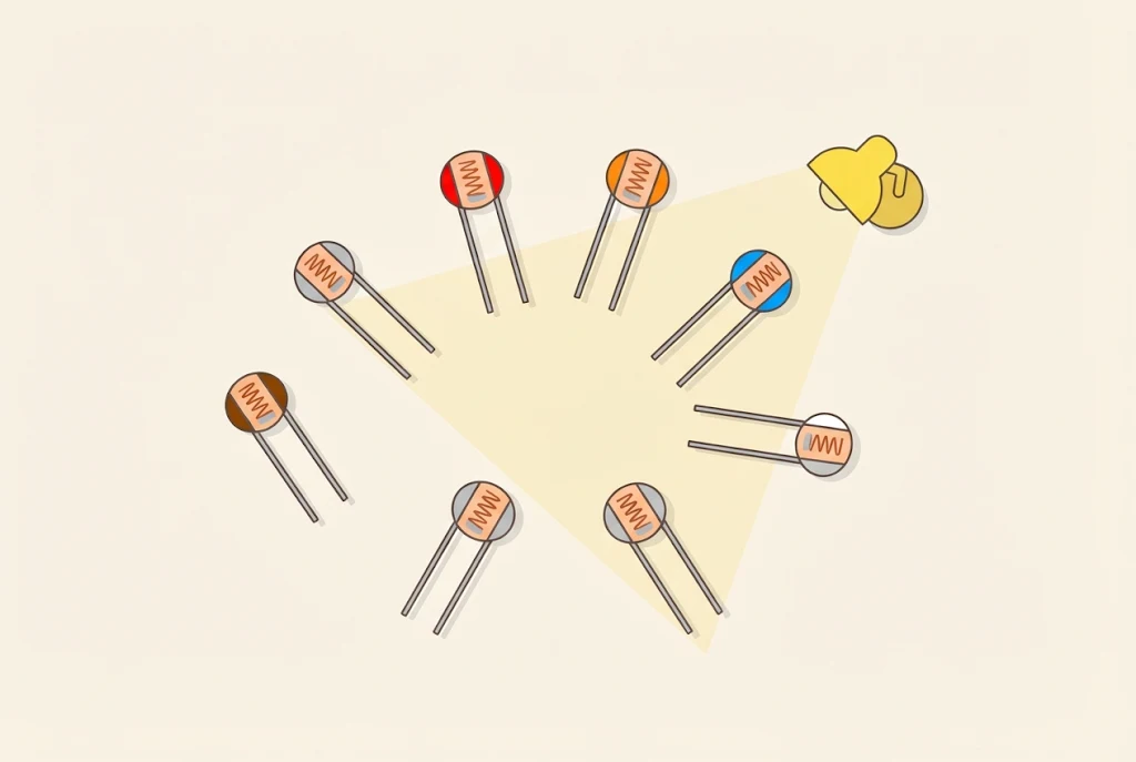
What is a photoresistor?
A photoresistor is a resistor whose resistance changes with light:
- more light ⇒ lower resistance, so current flows more easily;
- less light ⇒ higher resistance, so current flows less easily.
It is often called an LDR, a light dependent resistor. It doesn’t matter which way round you put it, because it has no plus or minus, just like an ordinary resistor.
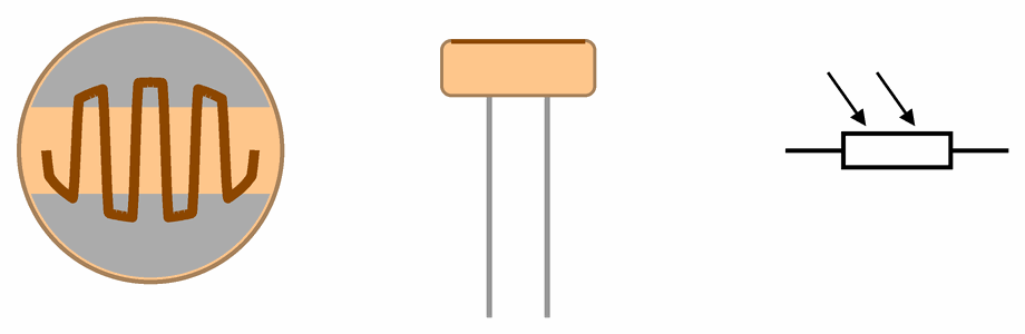
On top of a photoresistor you can see a wavy line. It is a thin layer of a material called cadmium sulphide. In the dark it conducts poorly. When light falls on it, the light frees charge carriers in it, so it conducts better. The grey parts on both sides of the line are metal and are joined to the legs. The line is wavy so that it is as long and as wide as possible, which makes the photoresistor more sensitive to light.
On the photoresistor’s symbol, two arrows show light falling on the resistor.
How much does its resistance change?
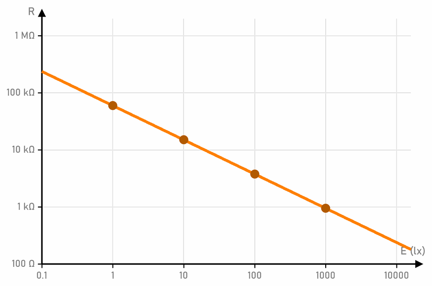
A lot. Light is measured in lux (lx). A lit classroom has about 300 to 500 lx, outdoors on a cloudy day there are a few thousand, and in the sun more than 50,000 lx. The graph shows the resistance of a GL5528 photoresistor, like ours:
| Light | Resistance |
|---|---|
| 1 lx (dusk) | about 60 kΩ |
| 10 lx (a dimly lit room) | about 15 kΩ |
| 100 lx (a room with the light on) | about 3.8 kΩ |
| 1000 lx (by a window in the daytime) | about 950 Ω |
On both axes each mark is ten times bigger than the one before. That way strong and weak light fit on one graph. When it is completely dark, the resistance rises above 1 MΩ.
The numbers are for one model. Two photoresistors of the same kind can differ by a factor of two, so measure each one first, for example with a multimeter set to resistance.
Where we use it
- Street lights turn on by themselves when it gets dark, and many plug-in night lights do the same.
- At the Arduino workshop we meet the photoresistor in Arduino - step by step: first it turns on an LED in the dark through a transistor, and then the Arduino reads the light.
- The micro:bit has no photoresistor, but it measures light with its LEDs. The light level block gives a number from 0 (dark) to 255 (bright light).
The photoresistor at the Arduino workshop
From here on, this page is for the Arduino workshop.
The voltage divider
The Arduino doesn’t measure resistance, but voltage. So the photoresistor goes into a voltage divider, with another resistor:
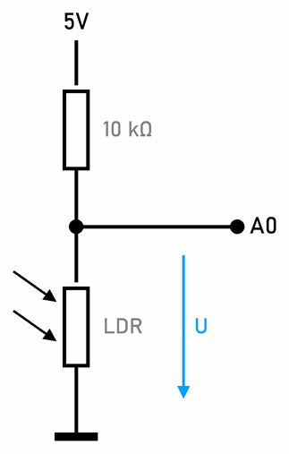
analogRead(A0) gives 614. When it gets darker, the photoresistor’s resistance rises and the voltage rises towards 5 V. When it gets brighter, the voltage falls towards 0 V.If you swap their places, so that the resistor goes to GND and the photoresistor to 5 V, everything turns around: then the voltage is high in the light. Both ways are fine, as long as the program knows which one it is.
Which resistor goes with the photoresistor?
The graph shows the voltage on A0 with a 1 kΩ, a 10 kΩ and a 100 kΩ resistor:
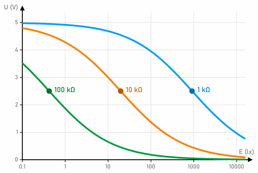
- 100 kΩ tells night-time light levels apart, below 1 lx;
- 10 kΩ tells dusk from a dimly lit room, around 20 lx;
- 1 kΩ tells daylight levels apart, around 900 lx. In the dark and indoors, the voltage with it is almost 5 V.
So we choose the resistor for the light we care about. In Arduino - step by step a potentiometer takes the place of the fixed resistor, so we set the limit by turning it.
A program: a light that turns on in the dark
The program reads A0 and turns on the Arduino’s built-in LED when it gets dark:
// C++
const int sensor = A0;                 // voltage divider: 10 kΩ to 5V, photoresistor to GND
const int DARK_LEVEL = 650;            // above this it is dark: turn the LED on
const int BRIGHT_LEVEL = 550;          // below this it is bright: turn the LED off

bool dark = false;                     // is the LED on now

void setup() {
  pinMode(LED_BUILTIN, OUTPUT);
  Serial.begin(9600);
}

void loop() {
  int reading = analogRead(sensor);    // 0 to 1023: the darker it is, the bigger the number
  float voltage = reading * 5.0 / 1023;  // the same number in volts

  if (!dark && reading > DARK_LEVEL) {
    dark = true;                       // it has got dark
  } else if (dark && reading < BRIGHT_LEVEL) {
    dark = false;                      // it has got bright
  }

  if (dark) {
    digitalWrite(LED_BUILTIN, HIGH);
  } else {
    digitalWrite(LED_BUILTIN, LOW);
  }

  Serial.print(reading);
  Serial.print("  ");
  Serial.print(voltage);
  Serial.println(" V");
  delay(200);
}
Why two limits? With one limit, say 600, the LED would flicker at dusk. When the light is right at the limit, the number jumps a little above it and a little below it, so the LED would keep turning on and off. With two limits the LED turns on when the number goes above 650 (about 8 lx), and off only when it drops below 550 (about 15 lx). In between, it stays as it was. A Hall sensor does the same, and so do street lights, which don’t turn on and off every time a cloud covers the sun.
Open the Serial Monitor, cover the photoresistor with your hand, then shine a phone’s torch on it. What numbers does it give in your classroom? Set the limits from your own numbers.
A photoresistor is slow
When the light changes suddenly, a photoresistor takes a few tens of milliseconds to change its resistance. For room light that doesn’t matter. A pinball ball blocks a beam of light for only about ten milliseconds, so a photoresistor wouldn’t notice it. That is a job for infrared sensors, which react in less than a millisecond.
Why are there fewer and fewer of them?
The cadmium in a photoresistor is poisonous. European Union rules (RoHS) restrict it in new devices, so factories increasingly use phototransistors and photodiodes instead, which are faster too. Some modules, such as the BH1750, measure light themselves and send the Arduino the number of lux over I2C. A photoresistor is safe to handle, but it never goes in the household rubbish, only with electronic waste.
 What did we learn?
- A photoresistor (LDR) has a lower resistance when it is brighter, and a higher one when it is darker. It has no plus or minus.
- The resistance changes a lot: from more than 1 MΩ in the dark to about a hundred Ω in the sun.
- The Arduino measures voltage, so the photoresistor goes into a voltage divider with a resistor.
- We choose the resistor so that it has the resistance the photoresistor has in the light we care about.
- Two limits stop the flickering around a limit. A photoresistor is slow, so for fast changes we use infrared sensors.
Quick quiz
1. What happens to a photoresistor's resistance when you cover it with your hand?
2. Why don't we connect a photoresistor to the Arduino on its own, but with another resistor?
3. The photoresistor is between A0 and GND, and 10 kΩ between 5V and A0. Is the voltage on A0 higher in the dark or in the light?
4. At 10 lx the photoresistor has 15 kΩ. What is the voltage on A0 with a 10 kΩ resistor?
analogRead(A0) gives about 614.5. You want a robot to tell a room from a sunny yard. Which resistor do you take: 1 kΩ, 10 kΩ or 100 kΩ?
6. Why does the program have two limits, 650 and 550, instead of one?