Pinouts: micro:bit, Arduino Uno, Nano, Mega and Giga
What each pin of the micro:bit (V1 and V2) and the Arduino Uno, Nano, Mega and Giga does: power, GND, digital and analog pins, PWM, I2C, SPI and UART.
What is a pin?
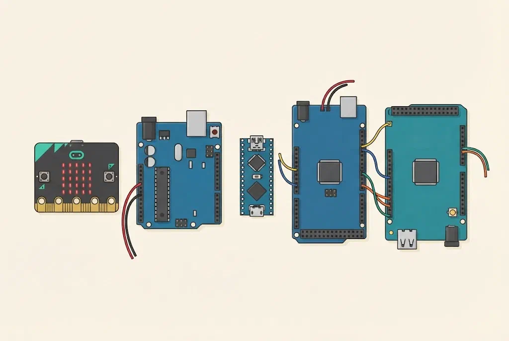
A pin is a place on a board where we connect a wire. Through its pins, a microcontroller sends and receives signals: it switches an LED on, reads a button or talks to a module. Some pins don’t carry signals, but give power (3V, 5V) or are connected to minus (GND).
Every pin has a name, printed on the board next to it. When you write pin P0 or digitalWrite(13, HIGH) in a program, you mean exactly that pin. A pinout is a map that shows where each pin is and what it can do. Without it, it is easy to connect a wire to the wrong pin, so the program doesn’t work or something gets damaged.
How to read a pinout
In the pictures on this page, each pin has a row of labels. The first one is the pin’s name, and the others tell you what else the pin can do. The colour of a label tells you what kind of pin it is:
| Label | What it means |
|---|---|
| 5V | power: 5V, 3V3, VIN, and 3V on the micro:bit |
| GND | minus, ground |
| D2 | digital pin: knows only 0 and 1 (LOW and HIGH) |
| A0 | Arduino analog input: measures a voltage, not just 0 and 1 |
| micro:bit analog input | |
| micro:bit pin that senses touch | |
| ~ | PWM: the pin switches on and off quickly, so an LED can shine dimmer or brighter |
| TX | UART connection (RX and TX) |
| SDA | I2C connection (SDA and SCL) |
| MOSI | SPI connection (MOSI, MISO, SCK and SS) |
| LED | a pin the board itself uses: an LED, the buttons, the display |
| RESET | special pins: RESET, AREF, IOREF, NC, and a pin you must not use |
UART, I2C and SPI are used to talk to modules. They are explained on the page How devices talk.
micro:bit
The big pins
On the bottom edge of the micro:bit there are five big pins with holes: P0, P1, P2, 3V and GND. We connect cables with crocodile clips to them, as in the lesson Lives and conditions.
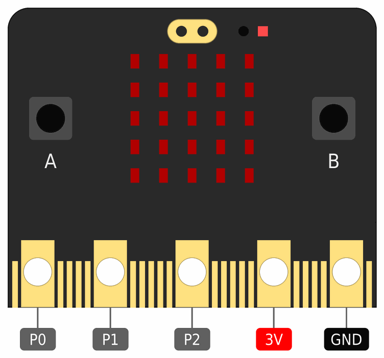
- P0, P1 and P2 are the pins for your parts. Each of them can switch an LED on, read a button, measure a voltage and sense touch. When you hold GND with one hand and touch P1 with the other, the micro:bit senses it with the pin P1 is pressed block.
- 3V gives a supply of about 3 V for what you connect. You may take only a little current from it: at most 90 mA on the micro:bit V1 and 190 mA on the micro:bit V2.
- GND is minus. Every part you connect to the micro:bit also needs a wire to GND.
The micro:bit works at 3 V
Never connect 5 V to a micro:bit pin, for example from an Arduino's 5V pin or from a USB charger. A voltage above 3.6 V can damage it for good. Why, is explained in misconception 9.
V1 or V2?
There are two main versions of the micro:bit. We call versions 1.3 and 1.5 V1, and versions 2.0 and 2.2 V2. Their pins are in the same places and have the same names, so parts are connected the same way. They differ in what they have on board:
| micro:bit V1 (1.3, 1.5) | micro:bit V2 (2.0, 2.2) | |
|---|---|---|
| Logo above the display | only printed | gold, senses touch |
| Microphone | none | yes, with a small hole and an LED next to the logo |
| Speaker | none, sound goes out on pin P0 | yes, on the back |
| Current from the 3V pin | at most 90 mA | at most 190 mA |
| I2C connection | shared by the sensors on the board and your modules | the sensors on the board have their own |
MakeCode programs work on both versions, except the blocks for the speaker, the microphone and the logo, which need a V2.
All the micro:bit’s pins
Between the big pins there are twenty narrow ones. A crocodile clip can’t hold on to them, so the micro:bit is plugged into a connector instead: into the Maqueen robot, or into a board that brings the pins out for a breadboard. In the picture, the micro:bit is turned so that all its pins are on the left, from P3 at the top to GND at the bottom. The V1 column shows what a micro:bit V1 uses each pin for, and the V2 column a micro:bit V2. The rows where they differ are shaded yellow: the display columns on P3, P4, P6, P7, P9 and P10, and the current you may take from the 3V pin.
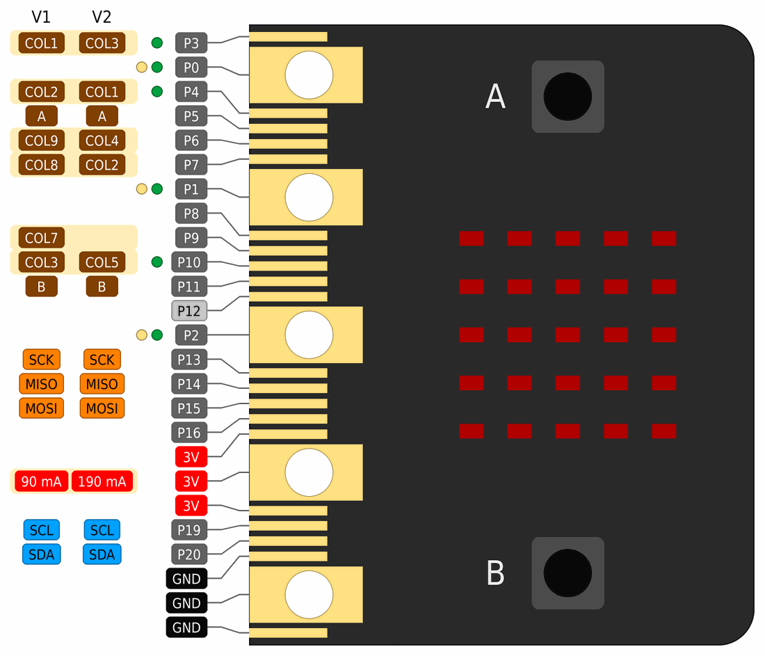
- The display and the buttons use some of the pins. The brown COL labels are the columns of LEDs on the display, and A and B are the buttons. While a program shows something on the display, the COL pins are busy. If you need them, switch the display off with the led enable false block.
- The analog inputs are P0, P1, P2, P3, P4 and P10, but P3, P4 and P10 are shared with the display.
- Touch is sensed by P0, P1 and P2, and on the micro:bit V2 also by the logo.
- P12 is reserved, so don’t use it for your parts.
- P13, P14 and P15 are the SPI connection, and P19 and P20 the I2C connection. On the micro:bit V1, the sensors on the board talk on the same I2C connection.
The Maqueen robot’s pins
The Maqueen robot uses these micro:bit pins:
| Pin | On the robot |
|---|---|
| P1 and P2 | the ultrasonic sensor (P1 sends the sound, P2 waits for the echo) |
| P8 and P12 | the left and the right red LED |
| P13 and P14 | the left and the right line sensor |
| P19 and P20 | the I2C connection to the chip that drives the motors (address 0x10) |
That is why the ultrasonic sensor and the bumper can’t be connected to the Maqueen at the same time: both use pin P1. The Maqueen also uses the reserved pin P12, for its right LED. That is fine, because the robot’s maker planned it that way.
Arduino
From here on, this page is for the Arduino workshop.
Arduino Uno
In the workshop we use the Arduino Uno. In the picture it is turned so that the USB socket is at the top. The digital pins are on the right, and the power pins and analog inputs on the left.
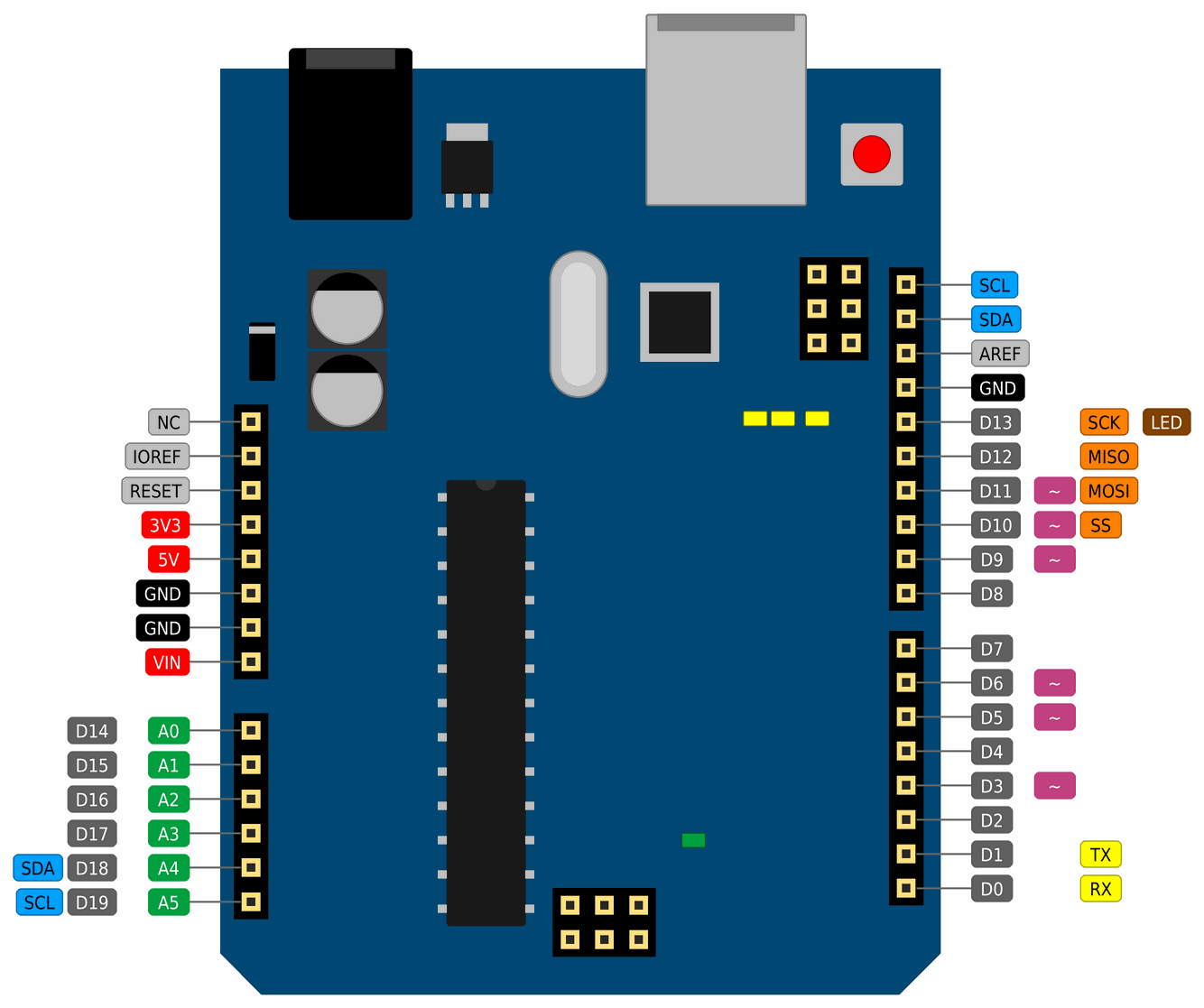
- D0 to D13 are the digital pins. You set them up with
pinMode()and use them withdigitalWrite()anddigitalRead(). - The pins with a wavy line (~), D3, D5, D6, D9, D10 and D11, can do PWM, so
analogWrite()works on them. PWM is explained in the lesson Voltage divider, Arduino and PWM. - A0 to A5 are the analog inputs. On them,
analogRead()measures a voltage from 0 to 5 V and returns a number from 0 to 1023, as in the lesson Arduino - step by step. They can also be ordinary digital pins, with the numbers 14 to 19. - D13 is connected to the L LED on the board, so the LED is on while the pin is
HIGH. - D0 and D1 are the UART connection, which is also connected to the USB. While something else is connected to them, uploading a program may fail.
- A4 and A5 are the I2C connection, and the same signals also come out on the SDA and SCL pins next to the AREF pin. D10 to D13 are the SPI connection.
- D2 and D3 can trigger an interrupt (
attachInterrupt()): the Arduino then reacts to a change on the pin straight away, even while it is doing something else.
The power pins:
- VIN is the voltage from the power socket. The Uno can also be powered through it, with 7 to 12 V.
- 5V and 3V3 give power for modules. The 3V3 pin gives at most 50 mA.
- GND is minus. The board has several GND pins, and they are all connected together.
- IOREF tells modules which voltage the board works at (5 V on the Uno), RESET restarts the program when you connect it to GND, and AREF can change the highest voltage that
analogRead()measures. NC (not connected) isn’t connected to anything.
The gap between pins D7 and D8 is bigger than between the others (4 mm instead of 2.54 mm). That is why a board with holes 2.54 mm apart can’t be pushed straight onto an Uno.
How much current an Arduino pin may give
- Take at most 20 mA from one pin. That is enough for an LED with a 220 Ω resistor, but not for a motor, a servo motor or a relay.
- All the pins together may give at most about 200 mA.
- Never connect a pin set as
OUTPUTstraight to GND or 5V. That is a short circuit, which can destroy the pin. - Don't bring more than 5 V to a pin, and don't connect a 9 V battery to the 5V pin. It goes to VIN or into the power socket.
Arduino Nano
The Nano has the same microcontroller as the Uno, the ATmega328P, so its pins are the same too: D0 to D13, PWM on the same pins, I2C on A4 and A5, SPI on D10 to D13. A program written for the Uno works on the Nano without changes. The Nano is much smaller (45 × 18 mm) and has its pins underneath, so you plug it into a breadboard across the middle gap.
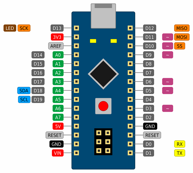
How it differs from the Uno:
- It has two more analog inputs, A6 and A7. They can only measure a voltage with
analogRead()and can’t be digital pins. - It has no power socket. It is powered over USB or through the VIN pin, with 7 to 12 V.
- Pins D0 and D1 are at the bottom of the right-hand row, not at the top.
Arduino Mega
The Mega 2560 has the ATmega2560 microcontroller, with many more pins and much more memory. We use it when the Uno doesn’t have enough pins, for example for many buttons and LEDs.
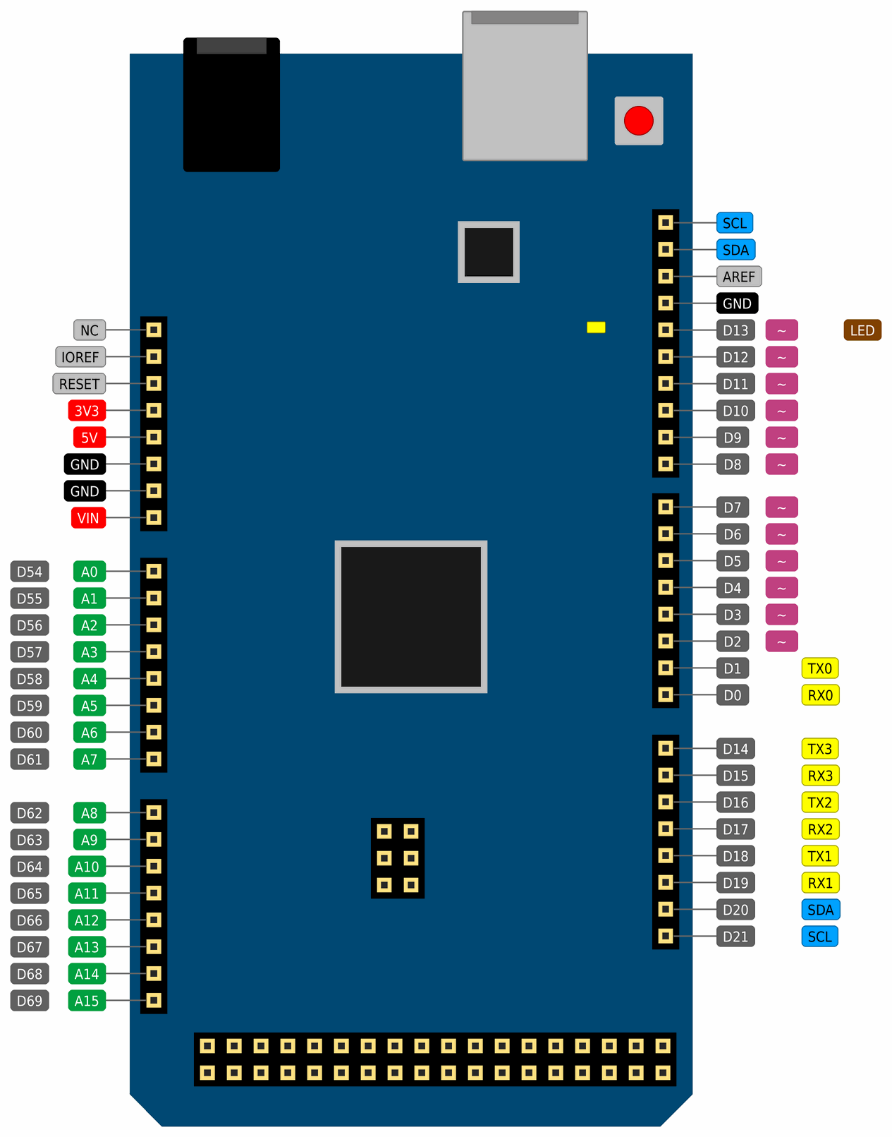
Pins 22 to 53 are in a double row at the end of the board. In the next picture the Mega is turned so that the USB socket is on the left and the double row stands upright: the even pins are in the inner row, and the odd pins along the edge of the board.
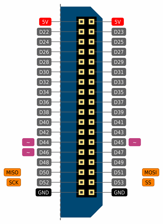
- D0 to D53 are digital pins, and D2 to D13 and D44 to D46 can do PWM.
- A0 to A15 are the analog inputs, and as digital pins they have the numbers 54 to 69.
- The Mega has four UART connections:
Serialon D0 and D1 (also connected to the USB),Serial1on D18 and D19,Serial2on D16 and D17, andSerial3on D14 and D15. So a module with a UART connection doesn’t have to go on pins 0 and 1. - D2, D3, D18, D19, D20 and D21 can trigger an interrupt.
- The power pins are the same as on the Uno.
I2C and SPI are on other pins on the Mega
On the Mega, the I2C connection isn't on A4 and A5, but on D20 (SDA) and D21 (SCL), and on the SDA and SCL pins next to the AREF pin. The SPI connection isn't on D10 to D13, but on D50 to D53. A module that worked on A4 and A5 or on D11 to D13 of an Uno has to be rewired on a Mega.
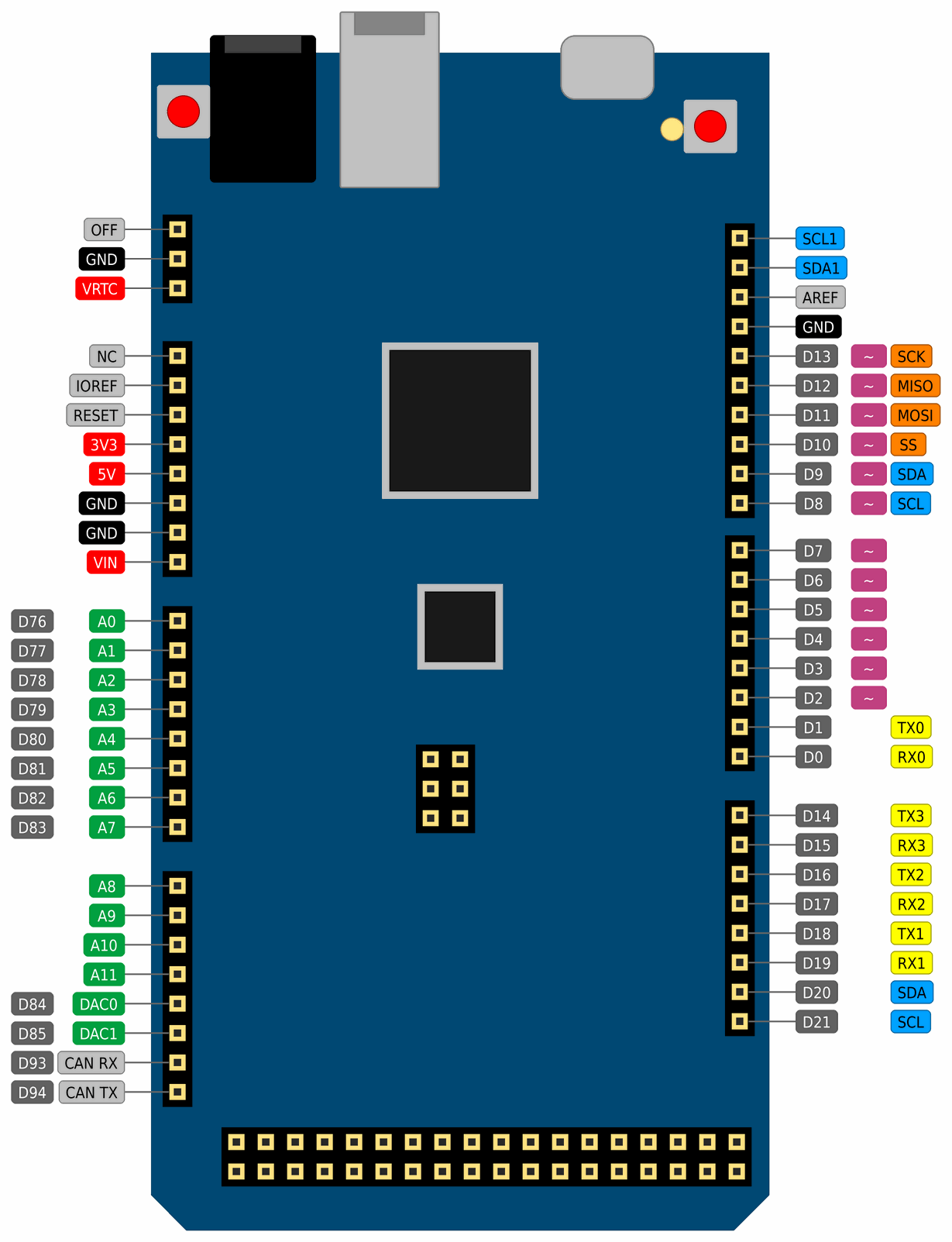
Arduino Giga R1 WiFi
The Giga has the same shape and the same headers as the Mega, but inside it is completely different. Its STM32H747XI microcontroller has two cores, at 480 MHz and 240 MHz, 2 MB of program memory and 1 MB of RAM, and the board adds 16 MB of flash memory and 8 MB of SDRAM. It has Wi-Fi and Bluetooth, an audio socket, connectors for a camera and a display, and two USB sockets. We use it for projects that need a lot of speed and memory, or a network connection.
The Giga works at 3.3 V
The Giga's pins work at 3.3 V, not at 5 V as on the Uno and the Mega. Don't bring 5 V to them, not even from a module that works at 5 V. Take at most 8 mA from one pin, and at most 140 mA from all of them together. A red LED with a 220 Ω resistor gets about 7 mA on the Giga, which is fine. A blue or white LED, which needs about 3 V, has too little voltage left, so it barely lights up.
How it differs from the Mega:
- It has three I2C connections: on D20 and D21, on the SDA1 and SCL1 pins next to the AREF pin, and on D8 and D9. On the Mega, D20 and D21 and the pins next to AREF are the same connection, but on the Giga they are two different ones.
- SPI is on D10 to D13, as on the Uno, and on six pins in the middle of the board.
- The four UART connections are on the same pins as on the Mega, but have other names in a program.
Serialgoes only over the USB-C socket to the Serial Monitor,Serial1is on D0 and D1,Serial2on D18 and D19,Serial3on D16 and D17, andSerial4on D14 and D15. So a Mega program that usesSerial1on D18 and D19 needsSerial2on the Giga. - D2 to D13 can do PWM. Pins 22 to 53 on the double row, arranged as on the Mega, are ordinary digital pins, without PWM and without SPI.
- A0 to A7 are analog inputs, and as digital pins they have the numbers 76 to 83. A8 to A11 can only measure a voltage.
- DAC0 and DAC1 are analog outputs: on them, the Giga makes a real voltage between 0 and 3.3 V, not PWM. The same signals also go to the audio socket.
- CAN RX and CAN TX are a CAN connection, which is used in cars and machines. It needs one more chip, a CAN transceiver.
- OFF switches the whole board off when you connect it to GND. VRTC takes a coin cell that keeps the microcontroller’s clock running while the board is off. The board can’t be powered through it.
- The board has an RGB LED on D86, D87 and D88, which lights up when the pin is
LOW. - It has no EEPROM. Data that must stay saved when the board is switched off is stored in flash memory instead: with the KVStore interface of Mbed OS, or on the board’s external 16 MB QSPI flash memory.
- VIN takes 6 to 24 V. The USB-C socket is for the computer and for power, and the USB-A socket only for devices such as a keyboard or a USB stick. The board can’t be powered through the USB-A socket.
- Wi-Fi and Bluetooth work only with an antenna connected to the small antenna socket next to the RESET button. The antenna comes with the board.
Uno, Nano, Mega and Giga side by side
| Uno | Nano | Mega 2560 | Giga R1 WiFi | |
|---|---|---|---|---|
| Microcontroller | ATmega328P | ATmega328P | ATmega2560 | STM32H747XI |
| Pin voltage | 5 V | 5 V | 5 V | 3.3 V |
| Current per pin | 20 mA | 20 mA | 20 mA | 8 mA |
| Digital pins | 14 (D0–D13) | 14 (D0–D13) | 54 (D0–D53) | 76 |
| PWM | 6 | 6 | 15 | 13 |
| Analog inputs | 6 (A0–A5) | 8 (A0–A7) | 16 (A0–A15) | 12 (A0–A11) |
| Analog outputs | – | – | – | 2 (DAC0, DAC1) |
| UART connections | 1 | 1 | 4 | 4 |
| I2C (SDA, SCL) | A4, A5 | A4, A5 | D20, D21 | D20, D21 and two more |
| SPI (MOSI, MISO, SCK, SS) | D11, D12, D13, D10 | D11, D12, D13, D10 | D51, D50, D52, D53 | D11, D12, D13, D10 |
| Program memory | 32 KB | 32 KB | 256 KB | 2 MB |
| Working memory (RAM) | 2 KB | 2 KB | 8 KB | 1 MB |
| EEPROM | 1 KB | 1 KB | 4 KB | none |
| Size | 69 × 53 mm | 45 × 18 mm | 102 × 53 mm | 101 × 53 mm |
How else these boards differ, how they are powered and which one to choose is on the Arduino boards page.
Names instead of numbers
The Arduino IDE knows, for every board, which pins are I2C, which are SPI and which one has the LED. So in a program you can write pin names instead of numbers: LED_BUILTIN, SDA, SCL, MOSI, MISO, SCK, SS and A0. When you choose another board, the name gets the right number, and the program works without changes. The Wire (I2C) and SPI libraries pick the right pins by themselves.
This program prints which number is behind each name:
// Prints which pin number is behind each name on this board.
// Upload it to an Uno, then to a Mega, and compare what the Serial Monitor shows.

void printPin(const char *name, int pin) {
  Serial.print(name);
  Serial.print(" = ");
  Serial.println(pin);
}

void setup() {
  Serial.begin(9600);
  printPin("LED_BUILTIN", LED_BUILTIN);
  printPin("A0", A0);
  printPin("SDA", SDA);
  printPin("SCL", SCL);
  printPin("MOSI", MOSI);
  printPin("MISO", MISO);
  printPin("SCK", SCK);
  printPin("SS", SS);
}

void loop() {
}
In the Serial Monitor, the Uno and the Nano print:
LED_BUILTIN = 13
A0 = 14
SDA = 18
SCL = 19
MOSI = 11
MISO = 12
SCK = 13
SS = 10
and the Mega:
LED_BUILTIN = 13
A0 = 54
SDA = 20
SCL = 21
MOSI = 51
MISO = 50
SCK = 52
SS = 53
A million micro:bits
The micro:bit was made by the BBC, the British broadcaster, with many partners. In 2016 it gave away about a million of them for free, to every pupil who started secondary school in the United Kingdom that year, at the age of 11 or 12.
 What did we learn?
- A pinout is a map that shows where each pin is and what it can do.
- The micro:bit has five big pins, P0, P1, P2, 3V and GND, and works at 3 V. We never connect 5 V to its pins.
- The micro:bit V1 and V2 have the same pins, but the V2 also has a speaker, a microphone and a logo that senses touch.
- The Uno and the Nano have the same pins: PWM on D3, D5, D6, D9, D10 and D11, I2C on A4 and A5, SPI on D10 to D13.
- The Mega has many more pins, but its I2C and SPI are on other pins than on the Uno.
- The Giga has the same headers as the Mega, but works at 3.3 V and gives at most 8 mA per pin.
- We take at most 20 mA from an Arduino pin, and in a program we write pin names instead of numbers.
Quick quiz
1. Which big pins does the micro:bit have?
2. May you connect a micro:bit pin to an Arduino's 5V pin?
3. How do you recognise a micro:bit V2 at first sight?
4. Which Arduino Uno pins can you connect an LED to if you want to change its brightness with analogWrite()?
5. An I2C module was connected to A4 and A5 on an Uno. Where do you connect it on a Mega?
6. May you connect a module that works at 5 V to the Giga's pins?
7. Why is it better to write LED_BUILTIN in a program than 13?