
Powering a project
Powering an Arduino project: USB, adapters and batteries, a power budget, linear regulators and buck converters, motors, common GND and fuses.
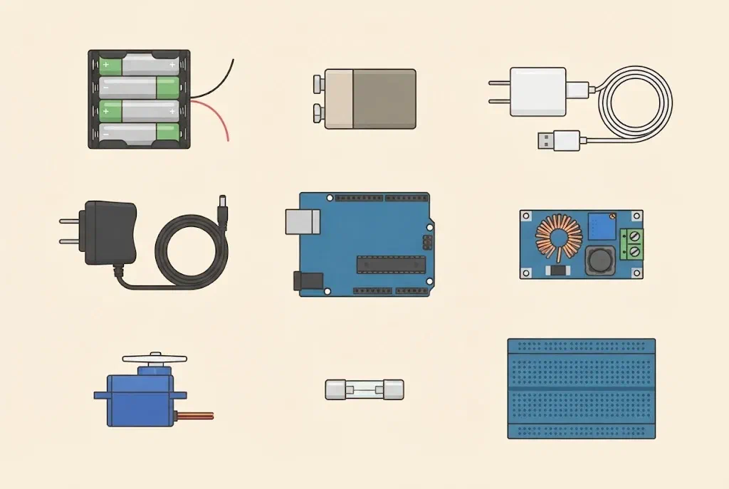
Where does a project get its power?
While the Arduino is on a USB cable, you don’t notice the power supply: the computer gives 5 V, and an Arduino, a few LEDs and a sensor use little. When a project gets motors, servos, LED strips or coils, or when it has to work without a computer, you have to decide where its power comes from and how much it needs.
This page is for the Arduino workshop (ages 12 and up). How 5 V is made from a higher voltage is on Rectifiers and voltage regulators, and which batteries there are on Batteries.
Power supply safety
Only use ready-made adapters and chargers with the CE mark that plug into a socket. Never open an adapter and never connect anything straight to a socket: 230 V can kill.
Power sources
- USB from a computer gives 5 V and about 500 mA (USB 2.0) or 900 mA (USB 3.0). Most Arduino Unos have a 500 mA resettable fuse on the USB input.
- A phone USB charger gives 5 V and 1 to 3 A, depending on the charger. It powers the Arduino and the project without a computer.
- An adapter (for example 9 V or 12 V, with a 5.5 × 2.1 mm DC plug) plugs into the Arduino Uno’s power socket. Arduino recommends 7 to 12 V for it.
- Batteries: four AA batteries give about 6 V, and a new 9 V battery gives little current and doesn’t last long. Four AA batteries are good for servos and small motors, but 6 V is too little for the Arduino’s power socket.
- A computer power supply (ATX) gives 12 V, 5 V and 3.3 V and a lot of current. It powers the pinball machine (see Power supply on the pinball page).
- A bench power supply has an adjustable voltage and a current limit. When you switch on a new circuit for the first time, set the current limit low: if there is a short circuit somewhere, nothing burns out.
How to power an Arduino Uno
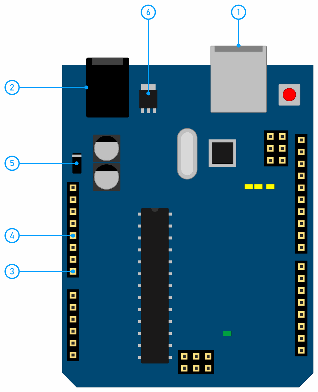
The Uno has four power inputs. Each has its own rules (the numbers are the same as in the picture):
| Input | Voltage | What to know |
|---|---|---|
| 1. USB | 5 V | a 500 mA fuse on most Unos |
| 2. power socket | 7–12 V | goes through a protection diode and a 5 V regulator |
| 3. VIN pin | 7–12 V | the same as the socket, but on most Unos without the protection diode: reversed polarity damages it |
| 4. 5V pin | exactly 5 V | bypasses the regulator and the protection; don’t connect it while the Uno is on USB |
The voltage from the power socket goes through the protection diode (5), which blocks the current when the adapter is the wrong way round, and then through the regulator (6), which makes 5 V from it. The VIN pin is connected after the diode, so the diode doesn’t protect it.
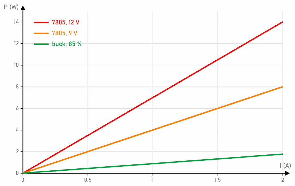
The Uno’s regulator is a linear one: it turns the extra voltage into heat. The higher the voltage on the socket, the less current the Uno can give on the 5V pin before the regulator overheats. The graph is on Arduino boards: Uno, Nano, Mega and Giga. That is why we don’t power motors and servos from the 5V pin but from a separate supply (see Motors and servos).
The Uno’s other limits: the 3.3V pin gives at most 50 mA, one pin 20 mA (at most 40 mA), and all pins together at most 200 mA.
How much current does a project need?
Before you choose a power supply, make a list of the loads and add up their currents. For each load take the largest current, not the average: a servo uses much more while it moves than while it stands still. An example for a project with two servos:
| Load | How many | Current |
|---|---|---|
| Arduino Uno | 1 | 50 mA |
| LEDs with resistors | 10 × 15 mA | 150 mA |
| active buzzer | 1 | 30 mA |
| SG90 servo, starting or stalled | 2 × 700 mA | 1400 mA |
| total | 1630 mA |
Add about a quarter to the total, for loads you have forgotten and for old batteries: 1630 mA · 1.25 ≈ 2 A. This project needs a 5 V supply of at least 2 A, for example a 2.4 A USB charger or a 3 A buck converter. USB from a computer (500 mA) wouldn’t be enough.
Measure the real current with a multimeter set to current, in series with the supply, and then update the list. The pinball machine has a list like this for the whole machine (see How much current does the pinball machine need?).
A linear regulator or a buck converter
When a project has a 12 V adapter and needs 5 V, the voltage has to come down. There are two kinds of circuit for that:
- A linear regulator (7805, AMS1117, the regulator on the Uno) lets the current through and throws away the extra voltage as heat: P = (Uin − 5 V) · I. From 12 V at 1 A that is 7 W, which can’t be cooled without a big heat sink. A linear regulator is good when the voltage difference or the current is small.
- A buck converter (a step-down converter, for example modules with an LM2596 or MP1584) switches the current on and off quickly and smooths it with a coil and a capacitor. It loses only part of the power, usually 10 to 20 %. The graph uses an efficiency of 85 %: at 1 A that is 0.88 W of heat, eight times less than a linear regulator from 12 V.
A buck converter also takes less current from 12 V than it gives: for 5 V and 2 A it takes about 1 A from 12 V, while a linear regulator takes the whole 2 A.
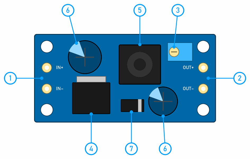
The most common buck module has an LM2596 chip. The numbers are the same as in the picture:
- IN+ and IN−: the input, where you connect the higher voltage (for example 12 V).
- OUT+ and OUT−: the output, with the lower voltage.
- The potentiometer that sets the output voltage. You turn it with a small screwdriver.
- The LM2596 chip, which switches the current on and off quickly.
- The coil, which smooths the current.
- The capacitors at the input and the output, which smooth the voltage.
- The diode, which carries the coil’s current while the chip is switched off.
IN− and OUT− are connected on the module: they are the common GND.
Set a buck converter before you connect it
Many buck modules have a potentiometer that sets the output voltage, and they arrive set to any voltage at all. Before you connect an Arduino or a servo to one, connect only its input, measure the output with a multimeter and turn the potentiometer to 5 V.
Motors and servos
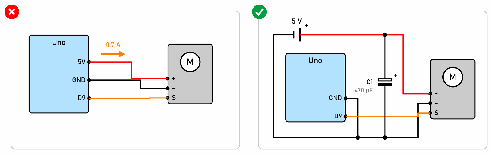
A motor or servo draws a much bigger current when it starts than when it runs, an SG90 servo up to 0.7 A. If you power it from the Arduino’s 5V pin:
- the 5 V drops for a moment, and the Arduino resets (starts the program again) or behaves strangely,
- the motor sends interference into the wires and the supply, so sensors give wrong values,
- the Uno’s regulator and USB fuse are overloaded.
That is why a motor has its own power supply, and shares only a common GND with the Arduino. Without a common GND, the signal from D9 has nothing to be measured against, so the servo doesn’t work (see misconception 8). The 470 µF capacitor C1 next to the servo supplies the current for its short peaks, so the voltage jumps less (see Capacitor).
An ordinary DC motor must not be connected straight to an Arduino pin, nor to the 5V pin: it needs a transistor, a MOSFET or a motor driver, and a protection diode across the coil of a motor or a relay (see Diode).
Powering a whole project
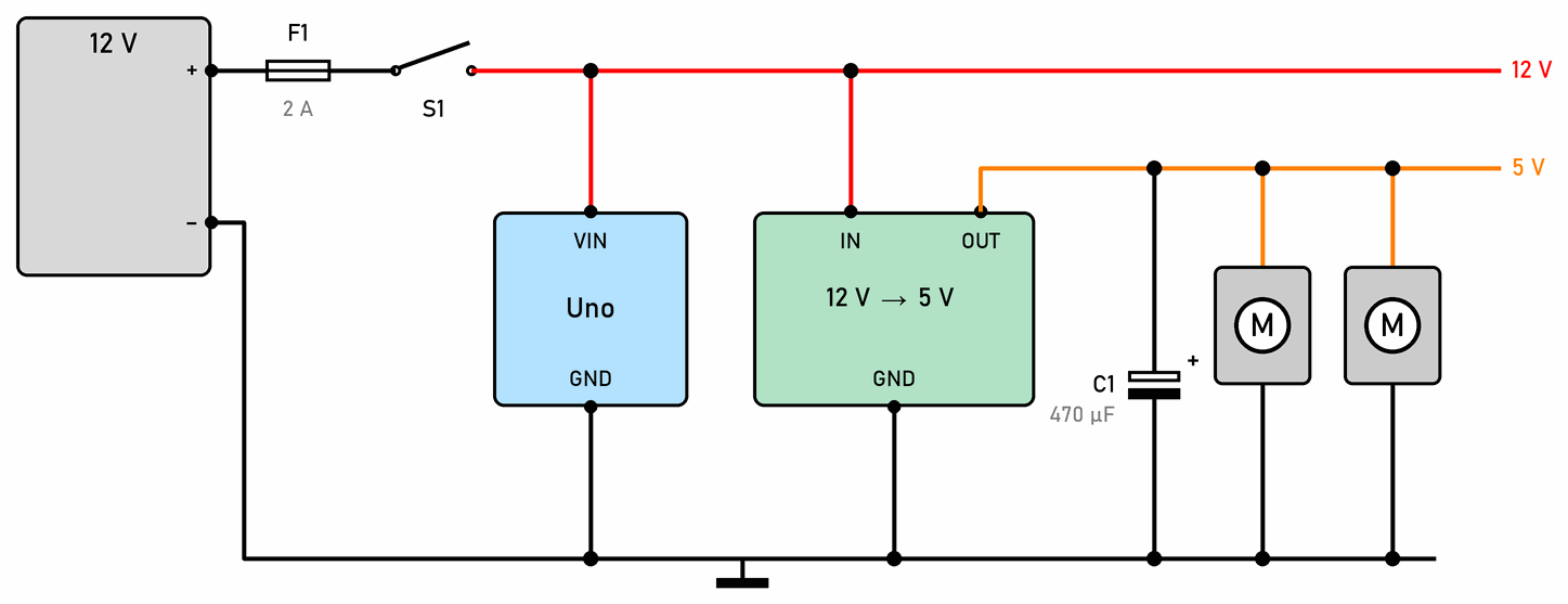
The schematic shows a typical project with a 12 V adapter:
- The fuse F1 is right at the adapter’s output. If a short circuit happens somewhere, the fuse blows before the wires catch fire. Choose one a little larger than the project’s largest current.
- The switch S1 turns off the whole project at once.
- The Arduino gets 12 V on its VIN pin. It uses little by itself, so its regulator doesn’t overheat.
- The buck converter makes 5 V for the servos and LEDs. The capacitor C1 is on its output.
- One GND joins all the parts. Large currents (motors) should go back to the adapter through their own wires, not through the Arduino’s GND.
Wires for large currents must be thick enough (see Wires, cables and connectors). Next to every chip we also put a 100 nF capacitor between its power and GND pins.
 What did we learn?
- USB from a computer gives 5 V and about 500 mA. For more current you need a USB charger, an adapter or a separate supply.
- Before you choose a supply, add up the largest currents of all the loads and add a quarter.
- A linear regulator turns extra voltage into heat. A buck converter loses much less, but it has to be set before you connect it.
- Motors and servos have their own power supply and share a common GND with the Arduino.
- The fuse goes right after the power source.
Quick quiz
1. A project has an Arduino (50 mA), four 15 mA LEDs and a servo that draws up to 700 mA. Is USB from a computer enough?
2. The Arduino resets every time the servo starts. What is the most likely cause?
3. How much heat does a linear regulator make if it gives 5 V and 0.5 A from 12 V?
4. You have bought a buck module. What do you do before you connect an Arduino to it?
5. A servo has its own 5 V supply, but it doesn't move. Its signal is on D9. What do you check?
6. Where in a project does the fuse go?