
Rectifiers and voltage regulators
How to get a steady 6 V from 9 V AC: the bridge rectifier, the smoothing capacitor, the 7806 regulator and regulators for currents of 3 to 5 A.
What is a rectifier?
The wall socket gives alternating voltage (AC). It changes direction 50 times a second: plus and minus keep swapping places. An Arduino, a micro:bit and LEDs need direct voltage (DC), where plus is always plus. The picture in misconception 20 shows what the two look like.
A rectifier is a circuit that turns alternating voltage into direct voltage. It is made of diodes. A diode lets current through in one direction only, like the turnstile at a stadium entrance: you can go in, but not back out.
A power supply that turns the socket’s voltage into a steady direct voltage has four parts:
- A transformer lowers the socket’s voltage to a low voltage. On this page that is 9 V of alternating voltage, written 9 V~.
- A rectifier of four diodes turns all the waves of the voltage to the same side.
- A filter with a capacitor smooths the voltage. A capacitor is like a bucket of water: it fills up while there is voltage and gives current when there isn’t.
- A voltage regulator turns the voltage, which still ripples a little, into a steady 6 V.
The socket's voltage is not for the workshop!
The voltage in a wall socket (230 V) can kill. You don't connect a transformer to the socket yourself either. At the workshop, 9 V~ comes from a closed adapter labelled 9V AC or 9V~. Most adapters today give direct voltage (DC), so check the label or ask the workshop leader.
A large electrolytic capacitor connected the wrong way round or to too high a voltage can swell and burst. The regulators and resistors in these circuits get hot enough to burn you.
From 9 V~ to 11.3 V
Alternating voltage changes all the time, so 9 V~ is not its highest voltage. It is the RMS value: an alternating voltage of 9 V~ heats a bulb just as much as a direct voltage of 9 V. It is also what a multimeter shows when it measures alternating voltage. The highest, peak voltage is √2 (about 1.41) times larger:
The bridge rectifier
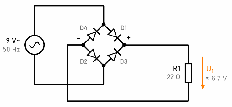
Four diodes connected in a diamond are called a bridge rectifier, or a Graetz bridge. You connect the alternating voltage of 9 V~ to the top and bottom corners of the diamond, and you get the direct voltage U1 between + (right) and – (left). The voltage arrow in the schematic points from plus to minus, in the direction of the current through the resistor. Here the load is a 22 Ω resistor R1.
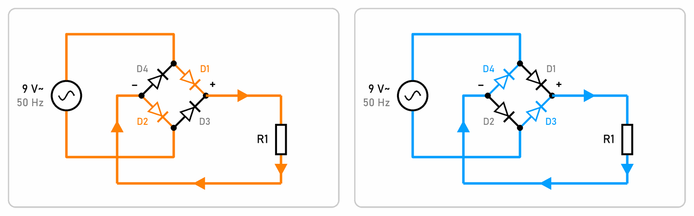
- When the top wire of the source is positive (left, orange), the current flows through D1 to plus, through R1 and back through D2.
- When the bottom wire is positive (right, blue), the current flows through D3 to plus, through R1 and back through D4.
Both times the current flows through the resistor in the same direction, from top to bottom. That is why the voltage across it is always positive.
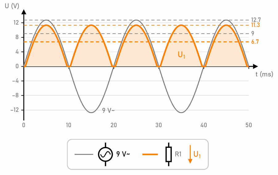
In the graph, the alternating voltage of 9 V~ is grey and the voltage U1 across the resistor R1 is orange. The negative waves are turned upwards, so instead of 50 waves a second you get 100 humps: one every 10 ms.
- The grey dashed line at 9 V is the source’s RMS value, the one a multimeter shows. The top of the grey wave is √2 times higher: 12.7 V.
- The top of a hump is 11.3 V, and the current through R1 is then 11.3 V / 22 Ω ≈ 0.51 A.
- Between the humps the voltage falls to 0 V. While the source’s voltage is below 1.4 V, the diodes don’t conduct.
- The average is about 6.7 V. That is what a multimeter shows when it measures direct voltage.
With one diode instead of four you would get a half-wave rectifier. It lets only the positive waves through, and for half the time there is nothing at the output. The bridge rectifier is a full-wave rectifier: it uses both halves.
This voltage is good enough for a bulb or a motor, but not for an Arduino. The voltage falls to zero 100 times a second, so the Arduino would keep restarting. The voltage has to be smoothed.
For the diodes you can use four 1N4007 (1 A) or a ready-made bridge rectifier with four legs, marked ~, ~, + and –.
Smoothing with a capacitor
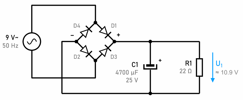
You connect the electrolytic capacitor C1 in parallel with the load, its plus to the rectifier’s plus. At every hump of the voltage the diodes conduct for a short time and charge the capacitor to 11.3 V. When the rectifier’s voltage falls, the diodes stop conducting and the capacitor gives the current for R1. While it does that, it slowly discharges and its voltage falls a little. Then the next hump comes and charges it again.
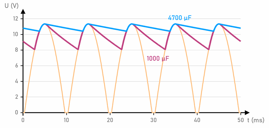
The voltage now looks like the teeth of a saw. The difference between the highest and the lowest voltage is called ripple. A bigger capacitor gives current for longer, so the ripple is smaller:
- with 1000 µF (purple) the voltage falls from 11.3 V to 8.1 V,
- with 4700 µF (blue) only to 10.4 V.
You can also calculate the ripple. The capacitor is charged 100 times a second (twice in every 50 Hz wave):
The average voltage is now about 10.9 V, close to the peak voltage, and the current through R1 is about 0.5 A. That is why this is the most common filter in power supplies.
What to watch out for:
- The capacitor’s polarity and voltage: a transformer with no load gives more than 9 V~, and the mains voltage varies a little too. That is why you use a 25 V capacitor and not a 16 V one. There is more about this in Electrolytic capacitors.
- The resistor’s power: R1 gets 10.9² V² / 22 Ω ≈ 5.4 W, so it needs to be a resistor of at least 10 W (see misconception 16).
- Diodes and transformer: the diodes conduct only briefly at the top of each hump, so the current through them then comes in pulses much larger than 0.5 A. When you switch the supply on, the empty capacitor briefly draws an even larger current (see misconception 17). So you choose the diodes and the transformer with a margin: a transformer of about 10 VA, even though 9 V · 0.5 A is only 4.5 VA.
- The capacitor stays charged after you switch the supply off. If you short it, it sparks (see misconception 22).
The 7806 voltage regulator
The voltage after the capacitor still ripples a little, and it also changes when the load’s current or the mains voltage changes. A voltage regulator turns it into a steady voltage. The 78xx regulators have the output voltage in their name: the 7805 gives 5 V, the 7806 gives 6 V, the 7809 gives 9 V, the 7812 gives 12 V. They have three legs: 1 is the input (IN), 2 is GND and 3 is the output (OUT). On the TO-220 package, the metal tab with the hole is connected to GND.
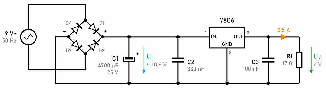
Next to the regulator you put two small ceramic capacitors, with the values from the regulator’s datasheet:
- C2 (330 nF) right at the regulator’s input. It is needed when C1 is more than a few centimetres away. Without it the regulator can start to oscillate.
- C3 (100 nF) at the output. It helps when the load suddenly changes its current. If the current changes a lot, you can also add a 10 to 100 µF electrolytic capacitor at the output.
Small capacitors next to chips are explained in misconception 19. The 12 Ω load R1 takes 6 V / 12 Ω = 0.5 A at 6 V.
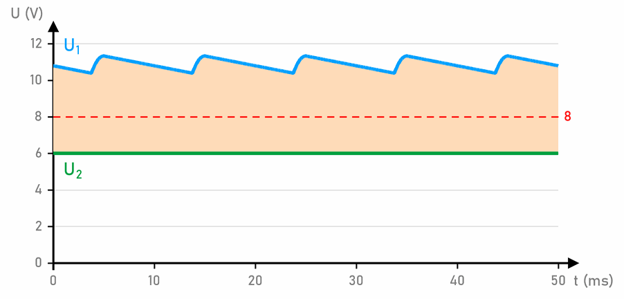
The input voltage U1 (blue) ripples between 10.4 V and 11.3 V, and the output voltage U2 (green) is a steady 6 V. The regulator turns all the extra voltage, the orange area in the graph, into heat.
A 78xx regulator needs at least 2 V more at its input than it gives at its output. For the 7806 that is 8 V (the red line), and at the lowest point of the ripple, not on average. With a 4700 µF capacitor the input doesn’t fall below 10.4 V, so there is a margin. Even when the mains voltage is 10 % lower, the lowest input voltage is about 9.2 V.
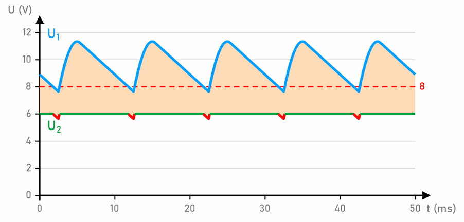
With a capacitor of only 1000 µF the input voltage falls to 7.6 V, below the red line. Then even the regulator can’t give 6 V: 100 times a second the output falls to 5.6 V (red). In an amplifier you hear this as a hum, and a sensitive circuit can behave strangely. So you choose the capacitor in front of the regulator by the load’s largest current.
How much current can a 78xx give?
78xx regulators come in three sizes:
- 78L06, in a small plastic package like a transistor (TO-92): up to 0.1 A,
- 78M06: up to 0.5 A,
- 7806 in a TO-220 package: up to 1 A (some datasheets say 1.5 A, with good cooling).
But usually heat sets the limit before current does. The regulator turns all the extra voltage into heat:
| Current | Lowest U1 (4700 µF) | Heat in the 7806 | Cooling |
|---|---|---|---|
| 0.1 A | 11.1 V | 0.5 W | no heatsink, about 25 °C warmer |
| 0.5 A | 10.4 V | 2.4 W | heatsink |
| 1 A | 9.6 V | 4.5 W | a larger heatsink, and a transformer of at least 20 VA |
A 78xx regulator has three built-in protections:
- current limiting, which protects it from a short circuit at the output,
- thermal protection, which switches it off when it overheats,
- protection at a large voltage difference: the larger the difference between input and output, the less current it allows.
These protections save the regulator, not the circuit. When they kick in, the output voltage falls or disappears. The circuit then works for a few minutes and stops, and when the regulator has cooled down, it works again. If this happens to you, the regulator needs a heatsink, a lower input voltage or a smaller current.
The highest input voltage for the 7806 is 35 V, but the higher the input voltage, the more heat. The same goes for the Arduino: most Uno boards have a linear 5 V regulator, so the recommended voltage on their power socket is 7 to 12 V. At 12 V the regulator gets warm, as in misconception 26.
Regulators for currents of 3 to 5 A
A 78xx regulator gives about 1 A at most. For 3 to 5 A there are two kinds of regulators.
Linear regulators work like the 7806, only for larger currents: the LM350 (3 A), the LM338 (5 A) and the LM1084 (5 A, with a smaller voltage drop, about 1.5 V). The LM350 and LM338 are adjustable: two resistors set the output voltage.
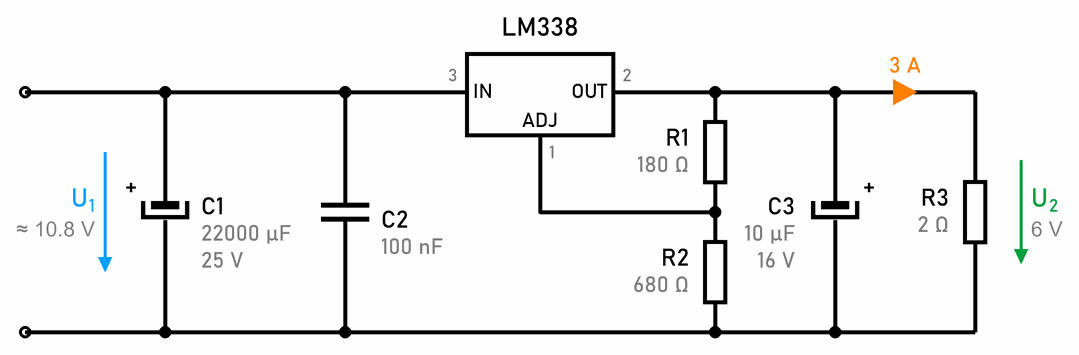
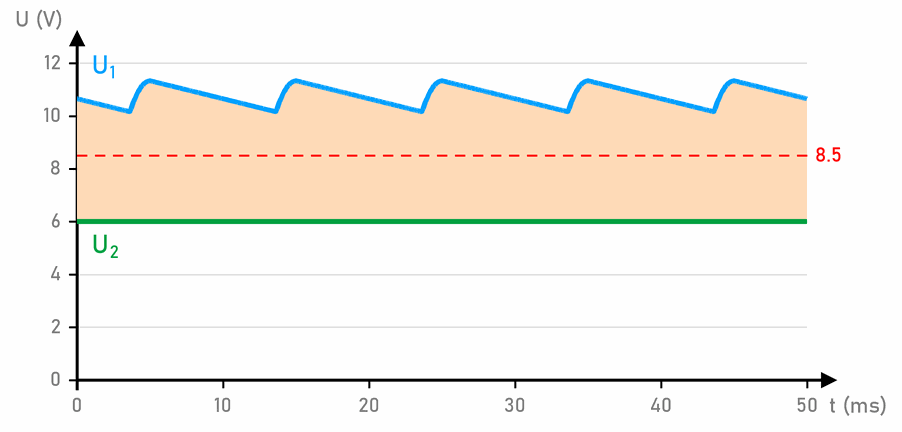
The input is the same bridge rectifier, but with larger diodes and a 22,000 µF capacitor, so that the input voltage doesn't fall below 8.5 V (6 V plus the regulator's voltage drop of about 2.5 V, the red line). The problem is heat. At 3 A the regulator turns (10.8 V − 6 V) · 3 A ≈ 14 W into heat. It needs a finned heatsink the size of your palm, or larger. For 5 A, 9 V~ wouldn't give enough voltage, and the heat would be over 20 W.
Switching regulators don't turn the extra voltage into heat. Instead, they switch the input voltage on and off very quickly. The LM2596 does this 150,000 times a second, and the coil L1 and the capacitor C3 turn these pulses into a steady voltage. While the internal switch is off, the current flows through the diode D1. Examples are the LM2596 and LM2576 (3 A), the LM2678 (5 A) and modules with the XL4015 chip (5 A). Here too, two resistors set the voltage:
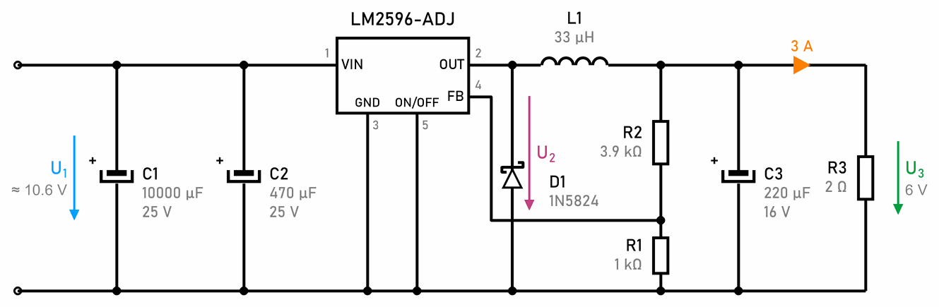
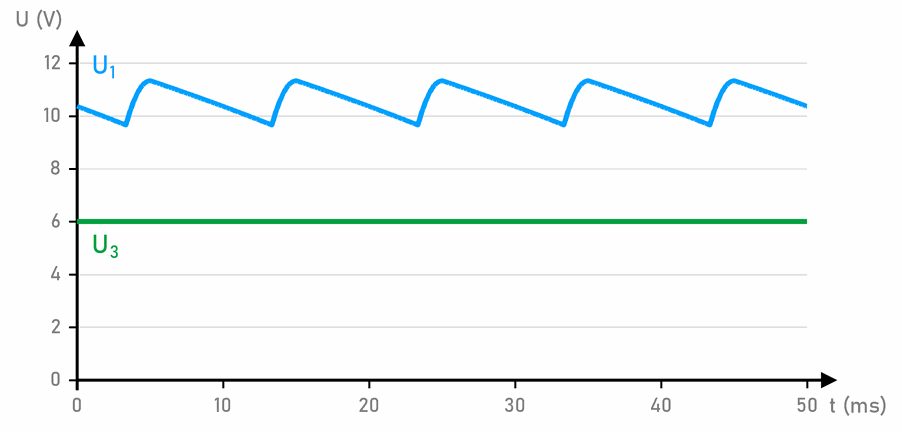
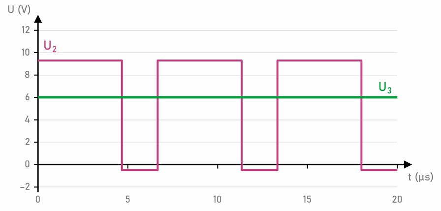
The first graph lasts 50 ms, like the earlier ones. The second lasts only 20 µs: the voltage U2 at the output leg jumps between about 9.3 V and −0.5 V (when D1 conducts). It is on for about 70 % of the time, and L1 and C3 turn that into an average: about 6 V.
A switching regulator uses 80 to 90 % of the energy. At 6 V and 3 A the load gets 18 W, and only about 3 W is lost in the regulator, instead of 14 W in the LM338. It takes only about 2 A from its input, less than it gives at its output, so a 10,000 µF capacitor C1 is enough.
What to watch out for with a switching regulator:
- The wires between C2, the chip, D1 and L1 must be short and thick. A breadboard is not good for this, and a circuit with long wires causes interference.
- D1 must be a fast Schottky diode. An ordinary 1N4007 diode is too slow and would overheat.
- The capacitors C2 and C3 must be made for switching power supplies (low ESR).
- Ready-made modules with the LM2596 or XL4015 are cheap and already well laid out. You set the output voltage with the potentiometer on the module and check it with a multimeter before you connect the load. Without extra cooling they give less current than the label says: an LM2596 module about 2 A.
At 3 to 5 A everything else has to be bigger too: a 40 to 60 VA transformer, a 6 to 10 A bridge rectifier with a heatsink (its two diodes lose about 6 W at 3 A), thick wires, screw terminals instead of a breadboard and a fuse after the transformer. Often the simplest and safest solution is a ready-made switching adapter (for example 12 V DC) and a switching regulator module.
 What did we learn?
- A rectifier of four diodes (a bridge rectifier) turns all the waves of an alternating voltage to the same side. From 9 V~ you get humps of up to 11.3 V, 100 times a second.
- The peak voltage is √2 times the RMS value, and about 0.7 V is lost on every diode that current flows through.
- A capacitor smooths the voltage. The bigger the capacitor, the smaller the ripple, and you can estimate it with the formula ΔU ≈ I / (2 · f · C).
- The 7806 regulator gives a steady 6 V if its input is always at least 8 V, even at the lowest point of the ripple.
- A linear regulator turns the extra voltage into heat, P = (U1 − U2) · I. That is why heat usually limits a 780x, not its 1 A of current.
- For 3 to 5 A switching regulators are better: they use 80 to 90 % of the energy.
Short quiz
1. What is the peak voltage of an alternating voltage of 12 V~?
2. Why are there 100, and not 50, humps of voltage a second at the output of a bridge rectifier?
3. Roughly how large is the ripple with a 2200 µF capacitor and a current of 0.5 A?
4. Why can't a 7806 regulator give 6 V if its input is 7 V?
5. How much heat is produced in a 7806 regulator when its input is 15 V and the load takes 0.4 A?
6. Why does a 3 A switching regulator need a much smaller heatsink than a linear LM338?
7. What can happen if you connect an electrolytic capacitor the wrong way round?