
Troubleshooting a circuit
How to find a fault step by step on a breadboard and on a printed circuit board: power, GND, looking, measuring voltage and continuity, splitting in half.
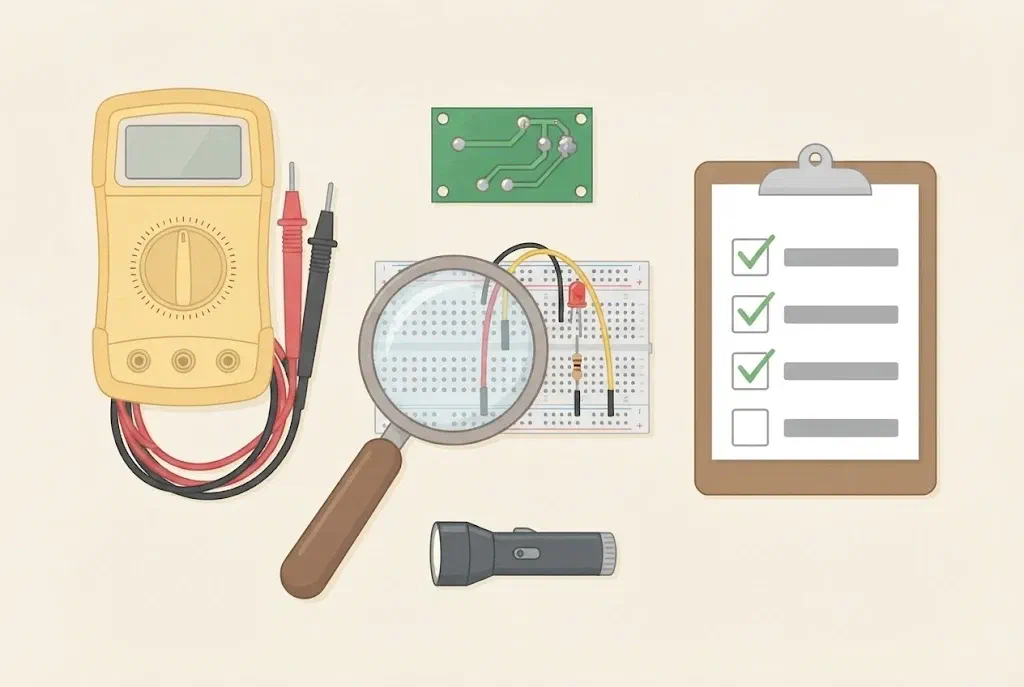
Hunting for a fault like a detective
The circuit doesn’t work. The worst thing you can do is change things at random: move a wire, turn an LED round, swap the Arduino, then something else. If the circuit works after that, you don’t know what the fault was, and if it doesn’t, you may have made a new one.
So we hunt for a fault like detectives: we watch, work things out and check one thing at a time, always in the same order. That way the fault is always found, and found faster.
Switch the power off before every change
- Move wires and components only while the power is off.
- If something gets hot, smokes or smells burnt, switch the power off at once and call the instructor.
- Measure resistance and continuity only without power.
The order of checks
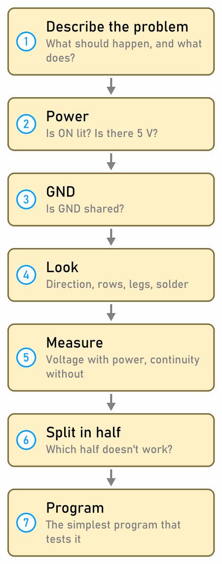
- Describe the problem. What should the circuit do, and what does it do? Has it ever worked? If it has, what changed last? The answer to that question often shows the fault straight away.
- Power. Is the ON LED on the Arduino lit? Measure the voltage on the breadboard’s power rails with a multimeter, not just on the Arduino. On a long breadboard the rails are sometimes split in the middle (see Split power rails). A battery can show a good voltage while nothing draws from it and drop when the circuit is switched on, so measure it while the circuit runs.
- GND. If the circuit has two power supplies or two boards, are their GNDs connected? Without a common GND, signals have nothing to be measured against.
- Look at the circuit. Switch the power off, take the schematic, and for every connection on it find the same connection in the circuit with your finger. Check which way round the LEDs, diodes, electrolytic capacitors and chips are (a notch or a dot marks pin 1), the resistor values, and that each wire is in the right pin and not the one next to it.
- Measure. With the power on, measure the voltages along the circuit (see Measuring voltage along a circuit). With the power off, check the continuity of wires and joints: the multimeter beeps when two points are connected.
- Split in half. When a circuit has many parts, don’t check them one after another; check whether the first half works (see Split in half).
- Program. Try each part with the simplest program that uses it: an LED with a program that only switches that pin on, a button with a program that only prints its state. If that program works, the fault is in your program, not in the circuit.
While you hunt:
- Change one thing at a time, and check the circuit after each change.
- Write down what you have checked, so you don’t check the same thing twice.
- Swap a suspect part for a good one: an LED for another LED, a wire for another wire, a module for one you know works.
- Explain the circuit to someone, out loud, connection by connection. You often spot the fault just while you are explaining.
Faults on a breadboard
On a breadboard, faults are most often in the connections, not in the components:
- a wire has broken inside its insulation but looks fine from outside,
- a wire or a leg is in the next row, or in the next pin of the Arduino,
- both legs of a component are in the same row, so the row shorts them,
- a leg is bent under the component and isn’t in its hole,
- a hole that someone pushed a thick leg into doesn’t grip well any more.
Pictures of the most common mistakes and the procedure for a breadboard are on Breadboard.
Measuring voltage along a circuit
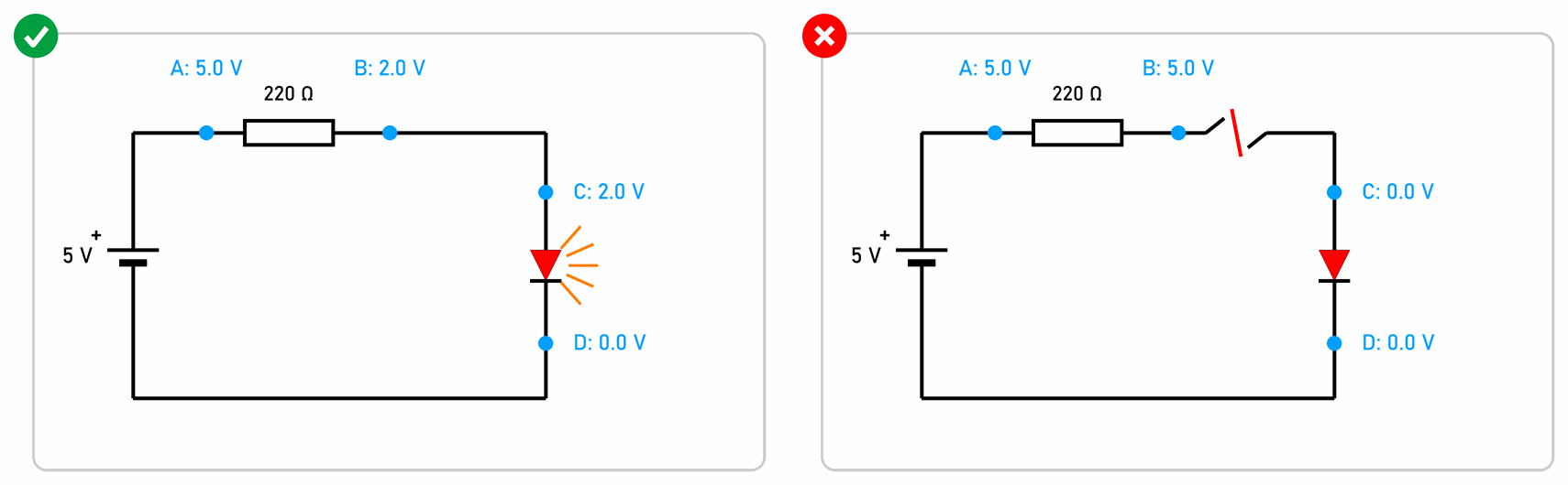
Put the multimeter’s black probe on GND and touch the points of the circuit one by one with the red probe, from the supply’s plus towards GND. The voltage may drop only across components, never along a wire:
- Left, the working circuit: at A there is 5 V. The resistor takes 3 V, so at B there is 2 V. The wire from B to C doesn’t change the voltage, so C is at 2 V too. The LED takes the remaining 2 V, so D is at 0 V. A current of (5 V − 2 V) / 220 Ω ≈ 14 mA flows round the circuit.
- Right, a broken wire: no current flows, so the resistor takes nothing and B is at the full 5 V. C is at 0 V. The voltage jumps from 5 V to 0 V between B and C, and there is only a wire between them. That is where the break is.
The rule: where the voltage jumps between two points joined only by a wire, there is a break. And if two points that should be different have the same voltage, there is a short circuit between them.
Split in half
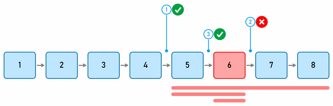
Many circuits are a chain of parts that the signal goes through in turn: power, switch, Arduino, transistor, relay, motor. Instead of checking part after part, measure the signal in the middle of the chain:
- Between blocks 4 and 5 the signal is right. So the fault is in blocks 5 to 8.
- Measure in the middle of what is left, between 6 and 7: the signal is wrong. The fault is in 5 or 6.
- Between 5 and 6 the signal is right, so the fault is in block 6.
Eight blocks need only three measurements, and sixteen need four. The procedure for a breadboard works the same way: split a circuit that doesn’t work into two parts and check each one separately.
Example: a motor on a button
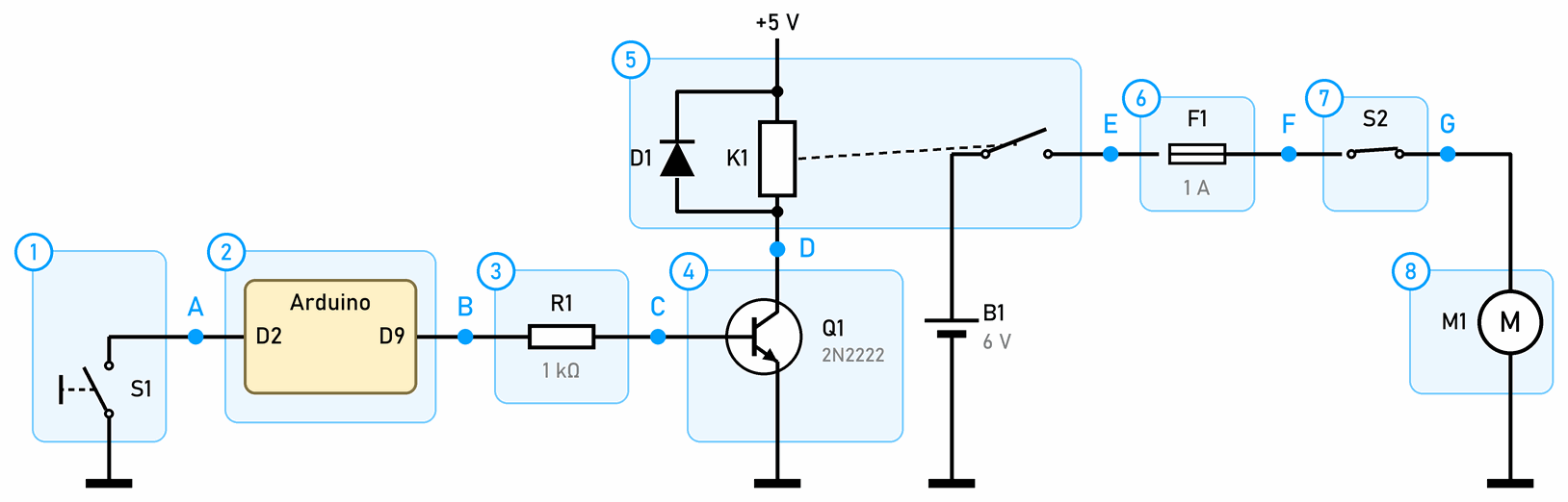
While you hold button S1, motor M1 should turn. S1 connects pin D2 to GND (D2 is set as INPUT_PULLUP), and the program then sets pin D9 HIGH. The current through resistor R1 switches transistor Q1 on, Q1 switches on the coil of relay K1, and the relay’s contact connects battery B1 to the motor through fuse F1 and switch S2. The circuit has the same eight blocks as the chain above, with test points A to G between them.
The motor doesn’t turn. The first three checks of The order of checks have passed: the ON LED is lit, B1 has 6 V, and GND is shared. The multimeter’s black probe stays on GND, and someone holds S1 down while you measure. Before you measure, write down what the voltage at each point should be:
| Point | Between blocks | Should be | Measured |
|---|---|---|---|
| A | 1 and 2 | 0 V | |
| B | 2 and 3 | 5 V | |
| C | 3 and 4 | 0.7 V | |
| D | 4 and 5 | 0.1 V | 0.1 V (1st measurement) |
| E | 5 and 6 | 6 V | 6 V (3rd measurement) |
| F | 6 and 7 | 6 V | 0 V (2nd measurement) |
| G | 7 and 8 | 6 V |
- The middle of the chain is point D, between blocks 4 and 5. The collector of transistor Q1 is at 0.1 V, which is right when Q1 is on. So the button, the Arduino with its program, R1 and Q1 work, and the fault is in blocks 5 to 8.
- The middle of what is left is point F, between blocks 6 and 7. It should be at 6 V, but the multimeter shows 0 V. The fault is in block 5 or 6.
- Point E, between blocks 5 and 6, is at 6 V, as it should be. The relay’s contact works, so the fault is in block 6, fuse F1.
Switch the power off, take F1 out and check it for continuity: the multimeter doesn’t beep, so the fuse has blown. Before you put in a new one, find out why it blew: was the motor stalled, or did its wires touch somewhere? The new fuse must have the same rating, 1 A: never a bigger one, and certainly not a piece of wire.
You didn’t need to measure points A, B, C and G. Had you measured in order from point A, only the sixth measurement would have found the fault.
Faults on a printed circuit board
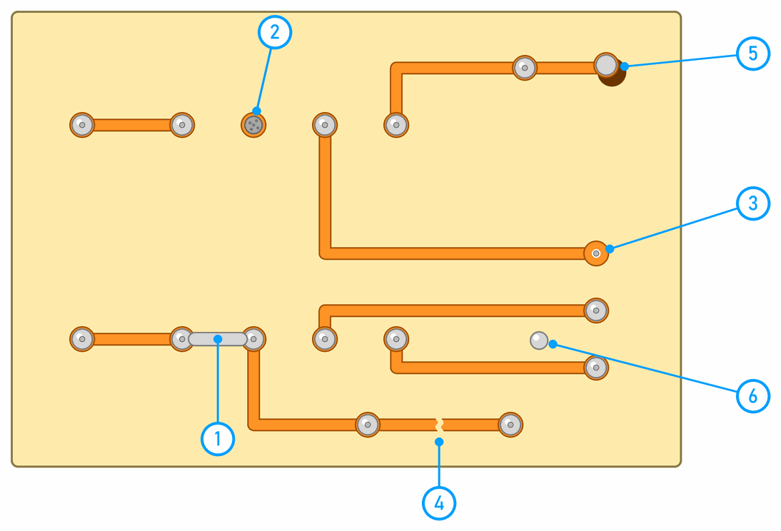
On a soldered board, faults are not as easy to see as on a breadboard. The numbers are the same as in the picture:
- A bridge of solder between two neighbouring joints (a short circuit).
- A cold joint: grey and grainy. It often works and then stops, especially when the board shakes.
- An unsoldered lead: easy to miss when you solder many leads in a row.
- A cracked track: a thin crack that you see only under a magnifier or when you hold the board up to the light.
- Lifted copper: from heating for too long. The track can be broken even when it looks whole.
- A drop of solder between tracks: it doesn’t join anything yet, but it can move and make a short circuit.
What a good and a bad joint look like and how to fix the faults is on Soldering.
A new board, step by step
- Inspect it under a magnifier and in good light, joint by joint. Check which way round the diodes, electrolytic capacitors and chips are, and the resistor values.
- Before you switch it on for the first time, measure the resistance between the supply’s plus and GND. It mustn’t be close to 0 Ω. (If the board has capacitors, the reading rises at first while the multimeter charges them.)
- Switch it on the first time from a bench power supply with a low current limit, or without the chips in their sockets.
- Watch whether anything gets hot or smells. If it does, switch off at once.
- Measure the voltage on the power pins of every chip.
- Compare it with a working board, if you have one: measure the same points on both. Where they differ, there is the fault.
- Resolder suspect joints: add a little flux and heat them until the solder flows.
When a circuit works and then doesn’t
The hardest fault to find is one that comes and goes. The most common causes:
- a cold joint or a loose wire (tap the board gently with a plastic stick while the circuit runs and watch when it fails),
- a motor or servo that pulls the voltage down when it starts and resets the Arduino (see Powering a project),
- an input pin without a pull-up or pull-down resistor, which is floating (see Buttons and switches),
- a part that overheats and stops working only after a while,
- static electricity that has damaged a chip (see Static electricity).
In the Arduino workshop
This part is for the Arduino workshop (ages 12 and up).
- Print what the program sees.
Serial.println()in the loop shows the state of a pin, the value of a sensor, or which part of the program is running. You read the output in the Serial Monitor. - Compare the pin numbers in the program and in the circuit. A common mistake is an LED on pin 7 and pin 6 in the program.
- Check
pinMode(). A pin that isn’t set asOUTPUTgives too little current for an LED to light fully, and a button withoutINPUT_PULLUPand without an external resistor reads random values. - Compile and upload errors are described on Arduino IDE.
 What did we learn?
- We hunt for a fault in order: describe the problem, power, GND, look at the circuit, measure, split in half, program.
- We change one thing at a time and write down what we have checked.
- Voltage drops only across components. Where the voltage jumps along a wire, there is a break.
- Splitting in half finds a fault among eight parts with three measurements.
- Before a new board is switched on for the first time, we inspect it and measure the resistance between plus and GND.
Quick quiz
1. The circuit worked yesterday and doesn't work today. What is the first question you ask?
2. An LED doesn't light. You measure 5 V on both sides of the resistor in front of it. What does that mean?
3. Why don't we change several things at once?
4. A chain has 16 parts. How many measurements does it take to find the faulty part by splitting in half?
5. What do you measure on a new board before you switch it on for the first time, and why?
6. The circuit works, but fails when you tap the board gently. What is the most likely cause?