
Wires, cables and connectors
Solid and stranded wire, wire gauge and voltage drop, wire colours, Dupont, JST, screw terminals and DC plugs, crimping and joining wires.
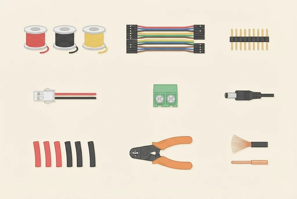
Wires and cables
A wire is a metal conductor, usually copper, that carries current. Round it is plastic insulation, so that the wire doesn’t touch another wire or metal and make a short circuit.
A cable is several wires in one shared sheath. A USB cable, for example, has four wires or more, and a headphone cable usually three.
Solid and stranded wire
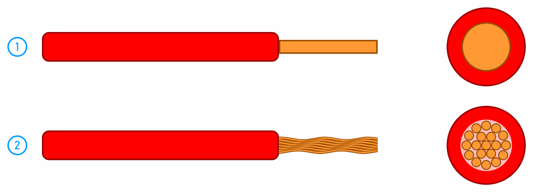
- Solid wire has one copper core. It keeps the shape you give it and goes into a breadboard easily, so it is good for wiring on a breadboard. If you bend it at the same spot many times, it breaks.
- Stranded wire has many thin strands. It is flexible and doesn’t break when it moves, so we use it for everything that moves: wires to the buttons and coils in the pinball machine, cables, jumper wires with pins on the ends. We don’t push it bare into a breadboard, because the strands fray. Its end is tinned (coated with solder), fitted into a connector or given a ferrule.
Wire colours
The colour of the insulation doesn’t change anything about the current. Colours are an agreement that helps you not to mix things up:
| Colour | What it usually means |
|---|---|
| red | the supply’s plus (5 V, 3.3 V, VCC) |
| black | GND (minus) |
| other colours | signals: Arduino pins, buttons, LEDs |
Some parts have colours of their own: a servo has a brown wire for GND, a red one for plus and an orange one for the signal, and a computer power supply (ATX) has yellow for 12 V, red for 5 V, orange for 3.3 V and black for GND (see the pinball machine).
The agreement doesn’t always hold, and someone may have broken it. When you aren’t sure, check with a multimeter.
Leave the wires in walls and mains devices alone
In house wiring and in devices that plug into a socket, the wires have other colours (brown, blue and green-and-yellow) and carry 230 V, which can kill. We never open or connect such wires and devices.
Connectors
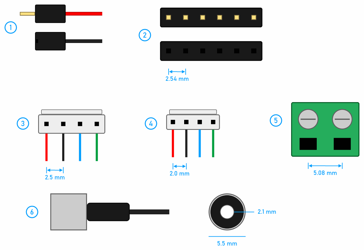
A connector joins a wire to a board or to another wire so that the joint can be taken apart. The numbers are the same as in the picture:
- Dupont jumper wires have a pin (male end) or a socket (female end) on their ends. We use them to connect the breadboard, the Arduino and modules.
- Pin headers have pins or sockets 2.54 mm apart (a tenth of an inch). The Arduino Uno has female headers, and the Nano and many modules have male ones. A breadboard’s holes have the same spacing, so all of these fit together.
- JST XH is a white connector with a 2.5 mm spacing. A LiPo battery’s balance lead has one, for example. The shape of the housing allows only one way round, so you can’t plug it in backwards.
- JST PH looks the same but is smaller, with a 2.0 mm spacing. The battery socket on the micro:bit is one. XH and PH are easy to mix up, but one doesn’t fit the other. Even smaller is JST SH (1.0 mm), which modules with Qwiic and STEMMA QT use.
- A screw terminal holds the wire with a screw. The most common spacing is 5.08 mm, and there are smaller ones of 3.5 mm. Larger currents can go through it, so we use it for power and coils.
- A 5.5 × 2.1 mm DC barrel plug is the round plug of a power adapter that fits the Arduino Uno’s power socket. On the Arduino the inner contact is plus and the outer one minus. The adapter shows this with a polarity symbol, so check that it matches.
Others you will meet: USB (power and data), XT60 (the yellow connector for the large currents of drone LiPo batteries) and the connectors of a computer power supply.
Joining wires
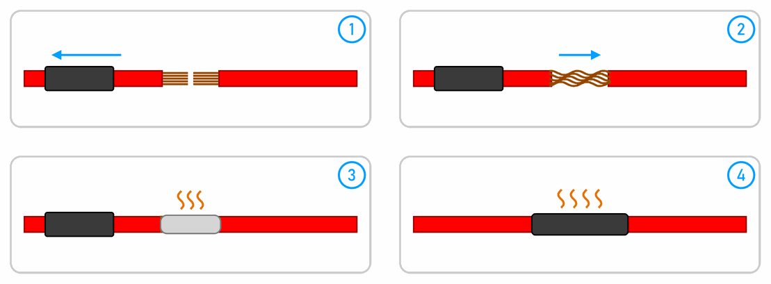
We join two wires by soldering, with an adult present (see Soldering):
- First slide heat-shrink tube onto one wire, away from the joint. If you forget it, you can’t get it on afterwards.
- Strip the insulation off both wires (about 1 cm) and twist the strands of one wire into the strands of the other.
- Solder the joint. The solder has to flow in among the strands, not just coat them.
- When the joint has cooled, slide the tube over it and heat it with a hot air gun. The tube shrinks and grips the joint tightly.
Insulating tape comes unstuck over time, so we don’t use it for permanent joints.
Tidy wiring
- Keep wires short, but not tight.
- Stick to the colours: red for plus, black for GND.
- Tie wires that go to the same place together with a cable tie, and label their ends (with a number or a sticker).
- Fix the wire to the board or the case, so that the pull doesn’t go onto the soldered joint when someone tugs the wire.
Wires in the Arduino workshop
This part is for the Arduino workshop (ages 12 and up).
Wire gauge
A wire’s thickness is the cross-section of its copper in square millimetres (mm²), or its AWG number (an American system). AWG works backwards: a bigger number means a thinner wire.
| AWG | Diameter (mm) | Cross-section (mm²) | Resistance of 1 m (Ω) | Where we use it |
|---|---|---|---|---|
| 28 | 0.32 | 0.08 | 0.21 | thin jumper wires, signals |
| 26 | 0.40 | 0.13 | 0.13 | jumper wires, signals |
| 24 | 0.51 | 0.20 | 0.08 | breadboard wires, LEDs |
| 22 | 0.64 | 0.33 | 0.05 | breadboard wires, power to modules |
| 20 | 0.81 | 0.52 | 0.03 | power, servos |
| 18 | 1.02 | 0.82 | 0.02 | coils and motors on 12 V |
The resistance is worked out with R = ρ · l / A, where l is the wire’s length, A its cross-section and ρ = 0.0172 Ω·mm²/m the resistivity of copper at 20 °C.
Voltage drop in a wire
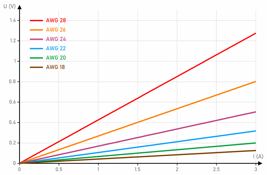
Current goes to the load through one wire and comes back through another, so for a device 1 m away we count 2 m of wire. By Ohm's law, the wire loses a voltage U = I · R:
- 2 m of AWG 28 wire at 1 A: 2 · 0.21 Ω · 1 A ≈ 0.42 V. Of 5 V, only about 4.6 V reaches the device.
- The same length of AWG 18 wire: only 0.04 V.
The lost voltage turns into heat in the wire (P = I² · R): in 2 m of AWG 28 wire at 2 A that is 1.7 W. That is why thin jumper wires are for signals and small currents, up to a few hundred milliamps. Motors, coils, LED strips and power go through thicker wires and screw terminals or better connectors. How to work out how much current a whole project needs is on Powering a project.
Crimping

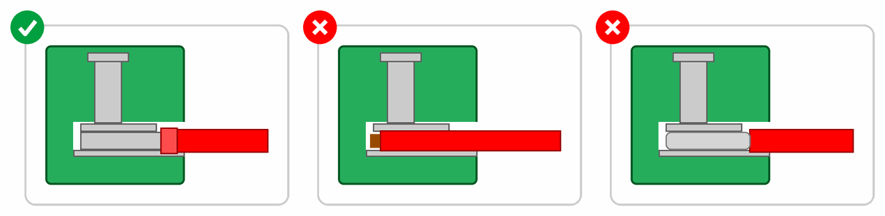
The contacts of Dupont and JST connectors aren’t soldered but crimped: special pliers (a crimping tool) squeeze the contact’s metal tabs round the wire. A contact has two pairs of tabs:
- the front ones, round the bare strands, which carry the current,
- the back ones, round the insulation, which hold the wire so it doesn’t pull out.
In the picture, the first contact is good. On the second, the insulation is pushed under the front tabs, so the strands don’t make good contact. On the third, a few strands stick out, and they can touch the next contact. After crimping, pull the wire gently: it mustn’t come out. Only then push the contact into the connector’s housing until it clicks.
A wire in a screw terminal
- A stranded wire goes into a screw terminal with a ferrule, a small metal tube crimped onto the strands. Without one, we twist the strands and push all of them under the screw.
- The screw must clamp the bare wire, not the insulation. Otherwise there is no contact, or a bad one, and you can’t see it from outside.
- We don’t tin a wire end that goes into a screw terminal. Solder under a screw slowly gives way, the joint works loose and starts to heat up.
After tightening, pull the wire gently. Tighten the screw terminals of a device that shakes (like the pinball machine) again after a few days.
 What did we learn?
- Solid wire keeps its shape and is good for a breadboard; stranded wire is flexible and good for anything that moves.
- A red wire is usually plus and a black one GND, but when you aren’t sure, check with a multimeter.
- Connectors differ in their pin spacing: Dupont 2.54 mm, JST XH 2.5 mm, JST PH 2.0 mm, a screw terminal usually 5.08 mm.
- Heat-shrink tube goes on before you solder.
- A bigger AWG number means a thinner wire. A thin wire loses more voltage and gets hotter, so large currents go through thick wires.
Quick quiz
1. Which wire do you use for a button that moves, solid or stranded? Why?
2. A wire is red. Does that mean for certain that it goes to plus?
3. You have soldered two wires together and only then remembered the heat-shrink tube. What now?
4. Which wire is thicker, AWG 18 or AWG 28?
5. A motor that draws 1 A is connected with 1 m jumper wires (AWG 28). How much voltage is lost in the wires?
6. Why don't we tin the end of a stranded wire that goes into a screw terminal?